Nissan Maxima. Manual - part 568
EXL-14
< SYSTEM DESCRIPTION >
[XENON TYPE]
AUTO LIGHT SYSTEM
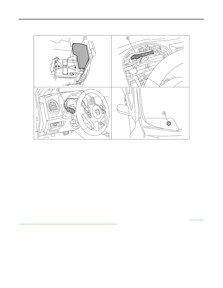
Component Parts Location
INFOID:0000000010050189
Component Description
INFOID:0000000010050190
AUTO LIGHT OPERATION
Applicable lamps
• Low beam headlamp
• Parking, license plate and tail lamps
• High beam headlamp (with the lighting switch in HIGH BEAM position)
• Front fog lamp (with the lighting switch in front fog lamp ON position)
When the lighting switch is in AUTO position with the ignition switch in ON position, BCM detects the AUTO
LIGHT (ON) by BCM combination switch (lighting and turn signal switch) reading function. BCM automatically
turns ON/OFF the applicable lamps according to ambient brightness.
NOTE:
Timing for when lamps turn ON/OFF can be changed by the function setting of CONSULT. Refer to
"HEADLAMP : CONSULT Function (BCM - HEAD LAMP)"
1.
IPDM E/R E17, E18, E200
2.
BCM M16, M17, M18, M19, M21 (view
with combination meter removed)
3.
Combination switch (lighting and turn
signal switch) M28
4.
Optical sensor M66
AWLIA1633ZZ