Nissan Maxima. Manual - part 564


  Index      Nissan     Nissan Maxima (2009-2014 year) - Service and Repair Manual


Search            


Content   ..  562  563  564  565   ..


Nissan Maxima. Manual - part 564


EX-4

< PERIODIC MAINTENANCE >

EXHAUST SYSTEM

PERIODIC MAINTENANCE

EXHAUST SYSTEM

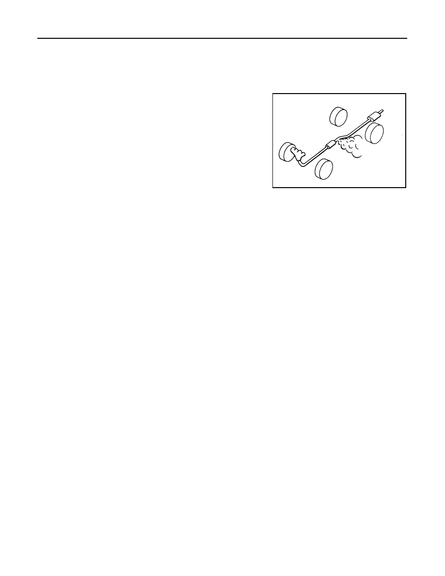
Checking Exhaust System

INFOID:0000000009464994

Check the exhaust pipes, muffler, and mounting components for

incorrect attachment, leaks, cracks, damage, or deterioration.

SMA211A

EXHAUST SYSTEM

EX-5

< REMOVAL AND INSTALLATION >

C

D

E

F

G

H

I

J

K

L

M

A

EX

N

P

O

REMOVAL AND INSTALLATION

EXHAUST SYSTEM

Exploded View

INFOID:0000000009464995

Removal and Installation

INFOID:0000000009464996

WARNING:

• Perform the procedures with the exhaust system fully cooled down to avoid injury from the hot

exhaust system. 

• Be careful not to cut your hand on the insulator edge.

CAUTION:

Use Genuine NISSAN exhaust system parts or equivalent, which are specifically designed for heat

resistance, corrosion resistance, and shape.

REMOVAL

• Remove exhaust system components using power tool.

• When removing center exhaust tube, remove tunnel stay bracket.

INSTALLATION

Installation is in the reverse order of removal.

CAUTION:

1.

Front exhaust tube

2.

Ring gasket

3.

Front exhaust tube stay 

4.

Front exhaust tube bracket  5.

Gasket

6.

Center exhaust tube rubber hanger

7.

Center exhaust tube

8.

Center exhaust tube hanger

9.

Rear muffler bracket (RH)

10. Rear muffler (RH)

11. Rear muffler bracket (LH)

12. Rear muffler (LH)

Front 

AWBIA1643ZZ

EX-6

< REMOVAL AND INSTALLATION >

EXHAUST SYSTEM

• Always replace exhaust gaskets with new ones when reassembling.

• If any insulator is badly deformed, repair or replace it. If deposits such as mud pile up on the insula-

tor, clean and inspect them.

• Temporarily tighten the nuts on the exhaust manifold side and the bolts on the vehicle side. Check

each part for interference with other components, and then tighten the nuts and bolts to specifica-

tion. 

INSPECTION AFTER INSTALLATION

• With the engine running, check the exhaust tube joints for exhaust gas leaks and unusual noises.

• Check that the mounting brackets and mounting insulators are installed properly and free from excessive

stress. Improper installation could result in excessive noise, leaks, and vibration. 

EXL-1

DRIVER CONTROLS

C

D

E

F

G

H

I

J

K

M

SECTION 

EXL

A

B

EXL

N

O

P

CONTENTS

EXTERIOR LIGHTING SYSTEM

XENON TYPE

BASIC INSPECTION  ....................................

6

DIAGNOSIS AND REPAIR WORKFLOW  ..........

6

Work Flow  .................................................................

6

SYSTEM DESCRIPTION  ..............................

9

HEADLAMP .........................................................

9

System Diagram ........................................................

9

System Description  ...................................................

9

Component Parts Location ........................................

9

Component Description ...........................................

10

DAYTIME RUNNING LIGHT SYSTEM  ..............

11

System Diagram ......................................................

11

System Description  .................................................

11

Component Parts Location ......................................

11

Component Description ...........................................

12

AUTO LIGHT SYSTEM  ......................................

13

System Diagram ......................................................

13

System Description  .................................................

13

Component Parts Location ......................................

14

Component Description ...........................................

14

FRONT FOG LAMP ............................................

15

System Diagram ......................................................

15

System Description  .................................................

15

Component Parts Location ......................................

15

Component Description ...........................................

16

TURN SIGNAL AND HAZARD WARNING 
LAMPS ...............................................................

17

System Diagram ......................................................

17

System Description  .................................................

17

Component Parts Location ......................................

17

Component Description ...........................................

18

PARKING, LICENSE PLATE AND TAIL 
LAMPS ...............................................................

19

System Diagram  ......................................................

19

System Description ..................................................

19

Component Parts Location  ......................................

19

Component Description  ...........................................

20

COMBINATION SWITCH READING SYSTEM 

...

21

System Diagram  ......................................................

21

System Description ..................................................

21

DIAGNOSIS SYSTEM (BCM)  ...........................

25

COMMON ITEM  .........................................................

25

COMMON ITEM : CONSULT Function (BCM - 
COMMON ITEM)  .....................................................

25

HEADLAMP ...............................................................

25

HEADLAMP : CONSULT Function (BCM - HEAD 
LAMP) ......................................................................

26

FLASHER ...................................................................

27

FLASHER : CONSULT Function (BCM - FLASH-
ER) ..........................................................................

27

COMB SW ..................................................................

27

COMB SW : CONSULT Function (BCM-COMB 
SW) ..........................................................................

27

BATTERY SAVER  .....................................................

28

BATTERY SAVER : CONSULT Function (BCM - 
BATTERY SAVER) ..................................................

28

DIAGNOSIS SYSTEM (IPDM E/R)  ...................

30

Diagnosis Description ..............................................

30

CONSULT Function (IPDM E/R)  .............................

32

DTC/CIRCUIT DIAGNOSIS  .........................

34

POWER SUPPLY AND GROUND CIRCUIT  ....

34

BCM (BODY CONTROL MODULE)  ..........................

34

BCM (BODY CONTROL MODULE) : Diagnosis 
Procedure ................................................................

34


Content   ..  562  563  564  565   ..