Nissan Maxima. Manual - part 491
EC-448
< DTC/CIRCUIT DIAGNOSIS >
[VQ35DE]
P1805 BRAKE SWITCH
P1805 BRAKE SWITCH
Description
INFOID:0000000010095150
Brake switch signal is applied to the ECM via the stop lamp switch when the brake pedal is depressed. This
signal is used mainly to decrease the engine speed when the vehicle is being driver.
DTC Logic
INFOID:0000000010095151
DTC DETECTION LOGIC
DTC CONFIRMATION PROCEDURE
1.
PERFORM DTC CONFIRMATION PROCEDURE
1. Turn ignition switch ON.
2. Fully depress the brake pedal for at least 5 seconds.
3. Erase the DTC.
4. Check 1st trip DTC.
Is 1st trip DTC detected?
YES
>> Go to
NO
>> INSPECTION END
Diagnosis Procedure
INFOID:0000000010095152
Regarding Wiring Diagram information, refer to
.
1.
CHECK STOP LAMP SWITCH CIRCUIT
1. Turn ignition switch OFF.
2. Check the stop lamp when depressing and releasing the brake pedal.
Is the inspection result normal?
YES
>> GO TO 4.
NO
>> GO TO 2.
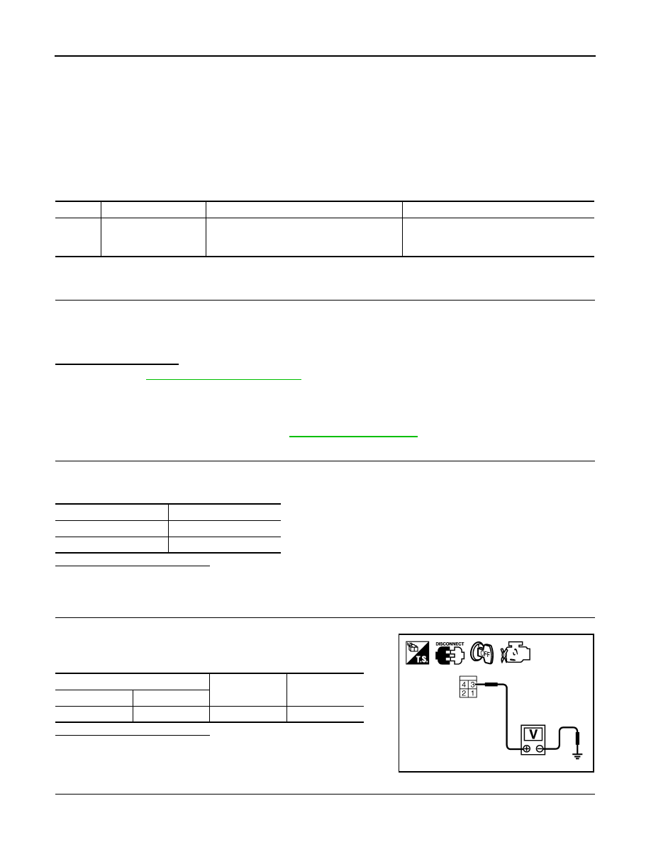
2.
CHECK STOP LAMP SWITCH POWER SUPPLY CIRCUIT
1. Disconnect stop lamp switch harness connector.
2. Check the voltage between stop lamp switch harness connector
and ground.
Is the inspection result normal?
YES
>> GO TO 4.
NO
>> GO TO 3.
3.
DETECT MALFUNCTIONING PART
Check the following.
DTC No. Trouble diagnosis name
DTC detecting condition
Possible cause
P1805
Brake switch
A brake switch signal is not sent to ECM for ex-
tremely long time while the vehicle is being driv-
er.
• Harness or connectors
(Stop lamp switch circuit is open or shorted.)
• Stop lamp switch
Brake pedal
Stop lamp
Fully released
Not illuminated
Slightly depressed
Illuminated
Stop lamp switch
Ground
Voltage
Connector
Terminal
E38
3
Ground
Battery voltage
PBIB2102E