Nissan Maxima. Manual - part 487


  Index      Nissan     Nissan Maxima (2009-2014 year) - Service and Repair Manual


Search            


Content   ..  485  486  487  488   ..


Nissan Maxima. Manual - part 487


EC-432

< DTC/CIRCUIT DIAGNOSIS >

[VQ35DE]

P1572 ASCD BRAKE SWITCH

4. Also check harness for short to ground and short to power.
Is the inspection result normal?

YES

>> GO TO 7.

NO

>> GO TO 6.

6.

DETECT MALFUNCTIONING PART

Check the following.

• Junction block connectors E45, E46

• Harness for open or short between ASCD brake switch and ECM

>> Repair open circuit, short to ground or short to power in harness or connectors.

7.

CHECK ASCD BRAKE SWITCH

Refer to 

EC-433, "Component Inspection (ASCD Brake Switch)"

Is the inspection result normal?

YES

>> GO TO 13.

NO

>> Replace ASCD brake switch. Refer to 

BR-18, "Removal and Installation"

.

8.

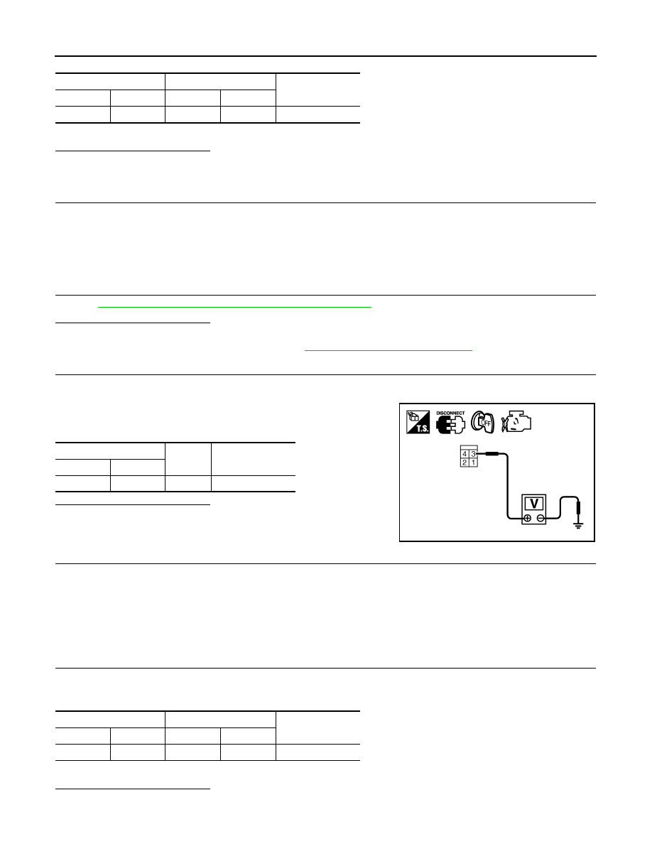
CHECK STOP LAMP SWITCH POWER SUPPLY CIRCUIT

1. Turn ignition switch OFF.

2. Disconnect stop lamp switch harness connector.

3. Check the voltage between stop lamp switch harness connector

and ground.

Is the inspection result normal?

YES

>> GO TO 10.

NO

>> GO TO 9.

9.

DETECT MALFUNCTIONING PART

Check the following.

• Fuse block (J/B) connector E6

• 10 A fuse (No. 7)

• Harness for open or short between stop lamp switch and battery

>> Repair open circuit, short to ground or short to power in harness or connectors.

10.

CHECK STOP LAMP SWITCH INPUT SIGNAL CIRCUIT FOR OPEN AND SHORT

1. Disconnect ECM harness connector.

2. Check the continuity between stop lamp switch harness connector and ECM harness connector.

3. Also check harness for short to ground and short to power.
Is the inspection result normal?

YES

>> GO TO 12.

ASCD brake switch

ECM

Continuity

Connector

Terminal

Connector

Terminal

E37

2

E10

110

Existed

Stop lamp switch

Ground

Voltage

Connector

Terminal

E38

3

Ground

Battery voltage

PBIB2102E

Stop lamp switch

ECM

Continuity

Connector

Terminal

Connector

Terminal

E38

4

E10

106

Existed

P1572 ASCD BRAKE SWITCH

EC-433

< DTC/CIRCUIT DIAGNOSIS >

[VQ35DE]

C

D

E

F

G

H

I

J

K

L

M

A

EC

N

P

O

NO

>> GO TO 11.

11.

DETECT MALFUNCTIONING PART

Check the following.

• Fuse block (J/B) connector E6

• Junction block connectors E44, E45

• Harness for open or short between stop lamp switch and ECM

>> Repair open circuit, short to ground or short to power in harness or connectors.

12.

CHECK STOP LAMP SWITCH

Refer to 

EC-433, "Component Inspection (Stop Lamp Switch)"

Is the inspection result normal?

YES

>> GO TO 13.

NO

>> Replace stop lamp switch. Refer to 

BR-18, "Removal and Installation"

.

13.

CHECK INTERMITTENT INCIDENT

Refer to 

GI-41, "Intermittent Incident"

.

>> INSPECTION END

Component Inspection (ASCD Brake Switch)

INFOID:0000000010095130

1.

CHECK ASCD BRAKE SWITCH-I

1. Turn ignition switch OFF.

2. Disconnect ASCD brake switch harness connector.

3. Check the continuity between ASCD brake switch terminals

under the following conditions.

Is the inspection result normal?

YES

>> INSPECTION END

NO

>> GO TO 2.

2.

CHECK ASCD BRAKE SWITCH-II

1. Adjust ASCD brake switch installation. Refer to 

BR-18, "Removal and Installation"

.

2. Check the continuity between ASCD brake switch terminals

under the following conditions.

Is the inspection result normal?

YES

>> INSPECTION END

NO

>> Replace ASCD brake switch. Refer to 

BR-18, "Removal

and Installation"

.

Component Inspection (Stop Lamp Switch)

INFOID:0000000010095131

1.

CHECK STOP LAMP SWITCH-I

1. Turn ignition switch OFF.

2. Disconnect stop lamp switch harness connector.

Terminals

Condition

Continuity

1 and 2

Brake pedal

Fully released.

Existed

Slightly depressed.

Not existed

SEC023D

Terminals

Condition

Continuity

1 and 2

Brake pedal

Fully released.

Existed

Slightly depressed.

Not existed

SEC023D

EC-434

< DTC/CIRCUIT DIAGNOSIS >

[VQ35DE]

P1572 ASCD BRAKE SWITCH

3. Check harness continuity between stop lamp switch terminals

under the following conditions.

Is the inspection result normal?

YES

>> INSPECTION END

NO

>> GO TO 2.

2.

CHECK STOP LAMP SWITCH-II

1. Adjust stop lamp switch installation. Refer to 

BR-14, "Inspection and Adjustment"

.

2. Check harness continuity between stop lamp switch terminals

under the following conditions.

Is the inspection result normal?

YES

>> INSPECTION END

NO

>> Replace stop lamp switch. Refer to 

BR-18, "Removal

and Installation"

.

Terminals

Condition

Continuity

3 and 4

Brake pedal

Fully released

Not existed

Slightly depressed

Existed

PBIB2103E

Terminals

Condition

Continuity

3 and 4

Brake pedal

Fully released

Not existed

Slightly depressed

Existed

PBIB2103E

P1574 ASCD VEHICLE SPEED SENSOR

EC-435

< DTC/CIRCUIT DIAGNOSIS >

[VQ35DE]

C

D

E

F

G

H

I

J

K

L

M

A

EC

N

P

O

P1574 ASCD VEHICLE SPEED SENSOR

Description

INFOID:0000000010095132

The ECM receives two vehicle speed signals via the CAN communication line. One is sent from combination

meter, and the other is from TCM (Transmission control module). The ECM uses these signals for ASCD con-

trol. Refer to 

EC-68, "System Diagram"

 for ASCD functions.

DTC Logic

INFOID:0000000010095133

DTC DETECTION LOGIC

NOTE:

• If DTC P1574 is displayed with DTC UXXXX, first perform the trouble diagnosis for DTC UXXXX.

• If DTC P1574 is displayed with DTC P0500, first perform the trouble diagnosis for DTC P0500. Refer

to 

EC-378, "DTC Logic"

.

• If DTC P1574 is displayed with DTC P0605, first perform the trouble diagnosis for DTC P0605. Refer

to 

EC-391, "DTC Logic"

.

• If DTC P1574 is displayed with DTC P0607, first perform the trouble diagnosis for DTC P0607. Refer

to 

EC-393, "DTC Logic"

.

DTC CONFIRMATION PROCEDURE

1.

PRECONDITIONING

If DTC Confirmation Procedure has been previously conducted, always perform the following before conduct-

ing the next test.

1. Turn ignition switch OFF and wait at least 10 seconds.

2. Turn ignition switch ON.

3. Turn ignition switch OFF and wait at least 10 seconds.

>> GO TO 2.

2.

PERFORM DTC CONFIRMATION PROCEDURE

1. Start engine (VDC switch OFF).

2. Drive the vehicle at more than 40 km/h (25 MPH).

CAUTION:

Always drive vehicle at a safe speed.

NOTE:

This procedure may be conducted with the drive wheels lifted in the shop or by driving the vehicle.

If a road test is expected to be easier, it is unnecessary to lift the vehicle.

3. Check DTC.
Is DTC detected?

YES

>> Go to 

EC-435, "Diagnosis Procedure"

.

NO

>> INSPECTION END

Diagnosis Procedure

INFOID:0000000010095134

1.

CHECK DTC WITH TCM

Check DTC with TCM. Refer to 

TM-36, "Diagnosis Description"

.

Is the inspection result normal?

DTC No.

Trouble diagnosis 

name

DTC detecting condition

Possible cause

P1574

ASCD vehicle speed 
sensor

The difference between the two vehicle speed 
signals is out of the specified range.

• Harness or connectors

(The CAN communication line is open or 
shorted.)

• Combination meter
• ABS actuator and electric unit (control unit)
• Wheel sensor
• TCM
• ECM


Content   ..  485  486  487  488   ..