Nissan Maxima. Manual - part 436


  Index      Nissan     Nissan Maxima (2009-2014 year) - Service and Repair Manual


Search            


Content   ..  434  435  436  437   ..


Nissan Maxima. Manual - part 436


EC-228

< DTC/CIRCUIT DIAGNOSIS >

[VQ35DE]

P0132, P0152 A/F SENSOR 1

3.

DETECT MALFUNCTIONING PART

Check the following.

• IPDM E/R harness connector F10

• 15 A fuse (No. 37)

• Harness for open or short between A/F sensor 1 and fuse

>> Repair or replace harness or connectors.

4.

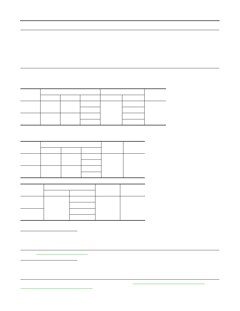
CHECK A/F SENSOR 1 INPUT SIGNAL CIRCUIT FOR OPEN AND SHORT

1. Turn ignition switch OFF.

2. Disconnect ECM harness connector.

3. Check the continuity between A/F sensor 1 harness connector and ECM harness connector.

4. Check the continuity between A/F sensor 1 harness connector and ground, or ECM harness connector

and ground.

5. Also check harness for short to power.
Is the inspection result normal?

YES

>> GO TO 5.

NO

>> Repair open circuit, short to ground or short to power in harness or connectors.

5.

CHECK INTERMITTENT INCIDENT

Perform 

GI-41, "Intermittent Incident"

.

Is the inspection result normal?

YES

>> GO TO 6.

NO

>> Repair or replace malfunctioning part.

6.

REPLACE AIR FUEL RATIO (A/F) SENSOR 1

Replace malfunctioning air fuel ratio (A/F) sensor 1. Refer to 

EM-31, "Removal and Installation (LH)"

 (LH) or

EM-33, "Removal and Installation (RH)"

 (RH).

CAUTION:

DTC

A/F sensor 1

ECM

Continuity

Bank

Connector

Terminal

Connector

Terminal

P0132

1

F12

1

F13

45

Existed

2

49

P0152

2

F61

1

53

2

57

DTC

A/F sensor 1

Ground

Continuity

Bank

Connector

Terminal

P0132

1

F12

1

Ground

Not existed

2

P0152

2

F61

1

2

DTC

ECM

Ground

Continuity

Connector

Terminal

P0132

F13

45

Ground

Not existed

49

P0152

53

57

P0132, P0152 A/F SENSOR 1

EC-229

< DTC/CIRCUIT DIAGNOSIS >

[VQ35DE]

C

D

E

F

G

H

I

J

K

L

M

A

EC

N

P

O

• Discard any A/F sensor which has been dropped from a height of more than 0.5 m (19.7 in) onto a

hard surface such as a concrete floor; use a new one.

• Before installing new A/F sensor, clean exhaust system threads using Oxygen Sensor Thread

Cleaner [commercial service tool (J-43897-18 or J-43897-12)] and approved anti-seize lubricant

(commercial service tool).

>> INSPECTION END

EC-230

< DTC/CIRCUIT DIAGNOSIS >

[VQ35DE]

P0137, P0157 HO2S2

P0137, P0157 HO2S2

Description

INFOID:0000000010094939

The heated oxygen sensor 2, after three way catalyst (manifold),

monitors the oxygen level in the exhaust gas on each bank.

Even if switching characteristics of the air fuel ratio (A/F) sensor 1

are shifted, the air-fuel ratio is controlled to stoichiometric, by the sig-

nal from the heated oxygen sensor 2.

This sensor is made of ceramic zirconia. The zirconia generates volt-

age from approximately 1 V in richer conditions to 0 V in leaner con-

ditions.

Under normal conditions the heated oxygen sensor 2 is not used for

engine control operation.

DTC Logic

INFOID:0000000010094940

DTC DETECTION LOGIC

The heated oxygen sensor 2 has a much longer switching time

between rich and lean than the air fuel ratio (A/F) sensor 1. The oxy-

gen storage capacity of the three way catalyst (manifold) causes the

longer switching time. To judge the malfunctions of heated oxygen

sensor 2, ECM monitors whether the maximum voltage of the sensor

is sufficiently high during various driving conditions such as fuel-cut.

DTC CONFIRMATION PROCEDURE

1.

INSPECTION START

Will CONSULT be used?

YES

>> GO TO 2.

NO

>> GO TO 5.

2.

PRECONDITIONING

If DTC confirmation Procedure has been previously conducted, always perform the following before conduct-

ing the next test.

1. Turn ignition switch OFF and wait at least 10 seconds.

2. Turn ignition switch ON.

3. Turn ignition switch OFF and wait at least 10 seconds.

TESTING CONDITION:

For better results, perform “DTC WORK SUPPORT” at a temperature of 0 to 30 

°C (32 to 86 °F).

>> GO TO 3.

SEF327R

JSBIA0243GB

DTC No.

Trouble diagnosis name

DTC detecting condition

Possible cause

P0137

Heated oxygen sensor 2 
(bank 1) circuit low volt-
age

The maximum voltage from the sensor does not 
reach the specified voltage.

• Harness or connectors

(The sensor circuit is open or shorted.)

• Heated oxygen sensor 2
• Fuel pressure
• Fuel injector
• Intake air leakage

P0157

Heated oxygen sensor 2 
(bank 2) circuit low volt-
age

P0137, P0157 HO2S2

EC-231

< DTC/CIRCUIT DIAGNOSIS >

[VQ35DE]

C

D

E

F

G

H

I

J

K

L

M

A

EC

N

P

O

3.

PERFORM DTC CONFIRMATION PROCEDURE

With CONSULT

1. Turn ignition switch ON and select “DATA MONITOR” mode with CONSULT.

2. Start engine and warm it up to the normal operating temperature.

3. Turn ignition switch OFF and wait at least 10 seconds.

4. Turn ignition switch ON.

5. Turn ignition switch OFF and wait at least 10 seconds.

6. Start engine and keep the engine speed between 3,500 and 4,000 rpm for at least 1 minute under no load.

7. Let engine idle for 1 minute.

8. Check that “COOLAN TEMP/S” indicates more than 70

°C (158°F).

If not, warm up engine and go to next step when “COOLAN TEMP/S” indication reaches 70

°C (158°F).

9. Open engine hood.

10. Select “HO2S2 (B1) P1147” (for DTC P0137) or “HO2S2 (B2) P1167” (for DTC P0157) of “HO2S2” in

“DTC WORK SUPPORT” mode with CONSULT display.

11. Follow the instruction of CONSULT.

NOTE:

It will take at most 10 minutes until “COMPLETED” is displayed.

12. Touch “SELF-DIAG RESULTS”.
Which is displayed on CONSULT screen?

OK

>> INSPECTION END

NG

>> Go to 

EC-233, "Diagnosis Procedure"

.

CANNOT BE DIAGNOSED>>GO TO 4.

4.

PERFORM DTC CONFIRMATION PROCEDURE AGAIN

1. Turn ignition switch OFF and leave the vehicle in a cool place (soak the vehicle).

2. Perform DTC confirmation procedure again.

>> GO TO 3.

5.

PERFORM COMPONENT FUNCTION CHECK

Perform component function check. Refer to 

EC-231, "Component Function Check"

.

NOTE:

Use component function check to check the overall function of the heated oxygen sensor 2 circuit. During this

check, a 1st trip DTC might not be confirmed.
Is the inspection result normal?

YES

>> INSPECTION END

NO

>> Go to 

EC-233, "Diagnosis Procedure"

.

Component Function Check

INFOID:0000000010094941

Regarding Wiring Diagram information, refer to 

EC-554, "Wiring Diagram"

.

1.

PERFORM COMPONENT FUNCTION CHECK-I

Without CONSULT

1. Start engine and warm it up to the normal operating temperature.

2. Turn ignition switch OFF and wait at least 10 seconds.

3. Turn ignition switch ON.

4. Turn ignition switch OFF and wait at least 10 seconds.

5. Start engine and keep the engine speed between 3,500 and 4,000 rpm for at least 1 minute under no load.

6. Let engine idle for 1 minute.


Content   ..  434  435  436  437   ..