Nissan Maxima. Manual - part 431


  Index      Nissan     Nissan Maxima (2009-2014 year) - Service and Repair Manual


Search            


Content   ..  429  430  431  432   ..


Nissan Maxima. Manual - part 431


EC-208

< DTC/CIRCUIT DIAGNOSIS >

[VQ35DE]

P0122, P0123 TP SENSOR

NO

>> Repair or replace ground connection.

2.

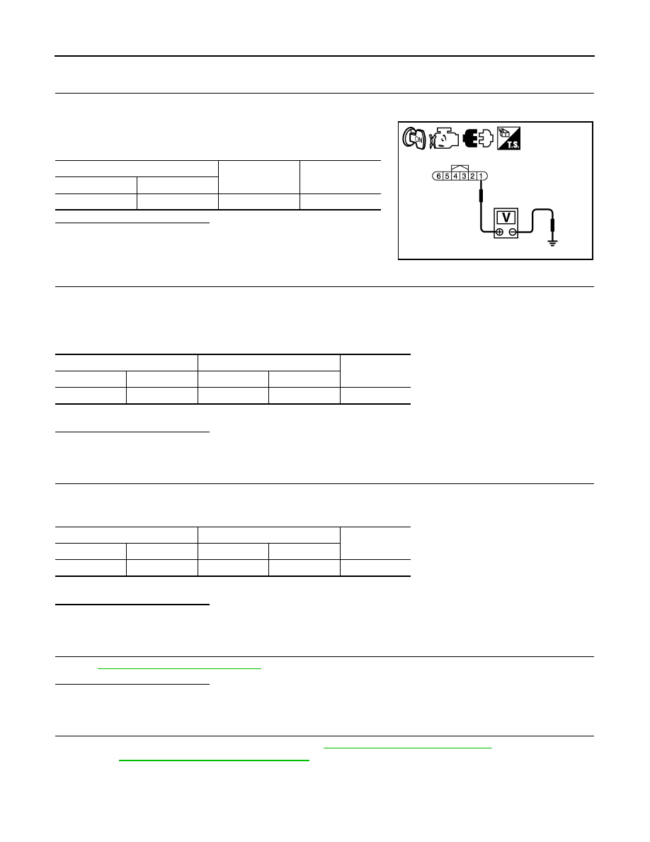
CHECK THROTTLE POSITION SENSOR 2 POWER SUPPLY CIRCUIT

1. Disconnect electric throttle control actuator harness connector.

2. Turn ignition switch ON.

3. Check the voltage between electric throttle control actuator har-

ness connector and ground.

Is the inspection result normal?

YES

>> GO TO 3.

NO

>> Repair open circuit, short to ground or short to power in

harness or connectors.

3.

CHECK THROTTLE POSITION SENSOR 2 GROUND CIRCUIT FOR OPEN AND SHORT

1. Turn ignition switch OFF.

2. Disconnect ECM harness connector.

3. Check the continuity between electric throttle control actuator harness connector and ECM harness con-

nector.

4. Also check harness for short to ground and short to power.
Is the inspection result normal?

YES

>> GO TO 4.

NO

>> Repair open circuit, short to ground or short to power in harness or connectors.

4.

CHECK THROTTLE POSITION SENSOR 2 INPUT SIGNAL CIRCUIT FOR OPEN AND SHORT

1. Check the continuity between electric throttle control actuator harness connector and ECM harness con-

nector.

2. Also check harness for short to ground and short to power.
Is the inspection result normal?

YES

>> GO TO 5.

NO

>> Repair open circuit, short to ground or short to power in harness or connectors.

5.

CHECK THROTTLE POSITION SENSOR

Refer to 

EC-209, "Component Inspection"

.

Is the inspection result normal?

YES

>> GO TO 7.

NO

>> GO TO 6.

6.

REPLACE ELECTRIC THROTTLE CONTROL ACTUATOR

1. Replace electric throttle control actuator.  Refer to 

EM-25, "Removal and Installation"

.

2. Refer to 

EC-209, "Special Repair Requirement"

.

>> INSPECTION END

Electric throttle control actuator

Ground

Voltage

Connector

Terminal

F57

1

Ground

Approx. 5 V

PBIB3484E

Electric throttle control actuator

ECM

Continuity

Connector

Terminal

Connector

Terminal

F57

4

F13

36

Existed

Electric throttle control actuator

ECM

Continuity

Connector

Terminal

Connector

Terminal

F57

3

F13

38

Existed

P0122, P0123 TP SENSOR

EC-209

< DTC/CIRCUIT DIAGNOSIS >

[VQ35DE]

C

D

E

F

G

H

I

J

K

L

M

A

EC

N

P

O

7.

CHECK INTERMITTENT INCIDENT

Refer to 

GI-41, "Intermittent Incident"

.

>> INSPECTION END

Component Inspection

INFOID:0000000010094916

1.

CHECK THROTTLE POSITION SENSOR

1. Turn ignition switch OFF.

2. Reconnect all harness connectors disconnected.

3. Perform 

EC-21, "THROTTLE VALVE CLOSED POSITION LEARNING : Special Repair Requirement"

.

4. Turn ignition switch ON.

5. Set selector lever to D position.

6. Check the voltage between ECM harness connector terminals

under the following conditions.

Is the inspection result normal?

YES

>> INSPECTION END

NO

>> GO TO 2.

2.

REPLACE ELECTRIC THROTTLE CONTROL ACTUATOR

1. Replace electric throttle control actuator. Refer to 

EM-25, "Removal and Installation"

.

2. Go to 

EC-209, "Special Repair Requirement"

.

>> INSPECTION END

Special Repair Requirement

INFOID:0000000010094917

1.

PERFORM THROTTLE VALVE CLOSED POSITION LEARNING

Refer to 

EC-21, "THROTTLE VALVE CLOSED POSITION LEARNING : Special Repair Requirement"

>> GO TO 2.

2.

PERFORM IDLE AIR VOLUME LEARNING

Refer to 

EC-21, "IDLE AIR VOLUME LEARNING : Special Repair Requirement"

>> END

ECM

Condition

Voltage

Con-

nector

+

Terminal

Terminal

F13

37

(TP sensor 

1 signal)

36

(Sensor 
ground)

Accelera-

tor pedal

Fully released

More than 0.36 V

Fully depressed

Less than 4.75 V

38

(TP sensor 

2 signal)

Fully released

Less than 4.75 V

Fully depressed More than 0.36 V

JMBIA1864ZZ

EC-210

< DTC/CIRCUIT DIAGNOSIS >

[VQ35DE]

P0125 ECT SENSOR

P0125 ECT SENSOR

Description

INFOID:0000000010094918

The engine coolant temperature sensor is used to detect the engine

coolant temperature. The sensor modifies a voltage signal from the

ECM. The modified signal returns to the ECM as the engine coolant

temperature input. The sensor uses a thermistor which is sensitive to

the change in temperature. The electrical resistance of the ther-

mistor decreases as temperature increases.

<Reference data>

*: These data are reference values and are measured between ECM terminals 46
(Engine coolant temperature sensor) and 52 (Sensor ground).

DTC Logic

INFOID:0000000010094919

DTC DETECTION LOGIC

NOTE:

• If DTC P0125 is displayed with P0116, first perform the trouble diagnosis for DTC P0116. Refer to 

EC-

201, "DTC Logic"

.

• If DTC P0125 is displayed with P0117 or P0118, first perform the trouble diagnosis for DTC P0117,

P0118. Refer to 

EC-204, "DTC Logic"

.

DTC CONFIRMATION PROCEDURE

1.

PRECONDITIONING

If DTC Confirmation Procedure has been previously conducted, always perform the following before conduct-

ing the next test.

1. Turn ignition switch OFF and wait at least 10 seconds.

2. Turn ignition switch ON.

3. Turn ignition switch OFF and wait at least 10 seconds.

>> GO TO 2.

2.

CHECK ENGINE COOLANT TEMPERATURE SENSOR FUNCTION

With CONSULT

1. Turn ignition switch ON.

SEF594K

Engine coolant temperature

[

°C (°F)]

Voltage* (V)

Resistance (k

Ω)

–10 (14)

4.4

7.0 - 11.4

20 (68)

3.5

2.1 - 2.9

50 (122)

2.2

0.68 - 1.00

90 (194)

0.9

0.236 - 0.260

SEF012P

DTC No.

Trouble diagnosis name

DTC detecting condition

Possible cause

P0125

Insufficient engine cool-
ant temperature for 
closed loop fuel control

• Voltage sent to ECM from the sensor is not 

practical, even when some time has passed 
after starting the engine.

• Engine coolant temperature is insufficient for 

closed loop fuel control.

• Harness or connectors

(High resistance in the circuit.)

• Engine coolant temperature sensor
• Thermostat

P0125 ECT SENSOR

EC-211

< DTC/CIRCUIT DIAGNOSIS >

[VQ35DE]

C

D

E

F

G

H

I

J

K

L

M

A

EC

N

P

O

2. Select “DATA MONITOR” mode with CONSULT.

3. Check that “COOLAN TEMP/S” is above 10

°C (50°F).

With GST

Follow the procedure “With CONSULT” above.
Is the temperature above 10

°C (50°F)?

YES

>> INSPECTION END

NO

>> GO TO 3.

3.

PERFORM DTC CONFIRMATION PROCEDURE

With CONSULT

1. Start engine and run it for 65 minutes at idle speed.

If “COOLAN TEMP/S” increases to more than 10

°C (50°F) within 65 minutes, stop engine because

the test result will be OK.

CAUTION:

Never overheat engine.

2. Check 1st trip DTC.

With GST

Follow the procedure “With CONSULT” above.
Is 1st trip DTC detected?

YES

>>

EC-211, "Diagnosis Procedure"

NO

>> INSPECTION END

Diagnosis Procedure

INFOID:0000000010094920

1.

CHECK GROUND CONNECTION

1. Turn ignition switch OFF.

2. Check ground connection E9. Refer to Ground Inspection in 

GI-44, "Circuit Inspection"

.

Is the inspection result normal?

YES

>> GO TO 2.

NO

>> Repair or replace ground connection.

2.

CHECK ENGINE COOLANT TEMPERATURE SENSOR

Refer to 

EC-211, "Component Inspection"

.

Is the inspection result normal?

YES

>> GO TO 3.

NO

>> Replace engine coolant temperature sensor. Refer to 

CO-24, "Removal and Installation"

.

3.

CHECK THERMOSTAT OPERATION

When the engine is cold [lower than 70

°C (158°F)] condition, grasp lower radiator hose and confirm that the

engine coolant does not flow.
Is the inspection result normal?

YES

>> GO TO 4.

NO

>> Repair or replace thermostat. Refer to 

CO-22, "Removal and Installation"

.

4.

CHECK INTERMITTENT INCIDENT

Refer to 

GI-41, "Intermittent Incident"

.

>> INSPECTION END

Component Inspection

INFOID:0000000010094921

1.

CHECK ENGINE COOLANT TEMPERATURE SENSOR

1. Turn ignition switch OFF.

2. Disconnect engine coolant temperature sensor harness connector.

3. Remove engine coolant temperature sensor. Refer to 

CO-24, "Removal and Installation"

.


Content   ..  429  430  431  432   ..