Nissan Maxima. Manual - part 374


  Index      Nissan     Nissan Maxima (2009-2014 year) - Service and Repair Manual


Search            


Content   ..  372  373  374  375   ..


Nissan Maxima. Manual - part 374


DOOR

DLK-215

< REMOVAL AND INSTALLATION >

C

D

E

F

G

H

I

J

L

M

A

B

DLK

N

O

P

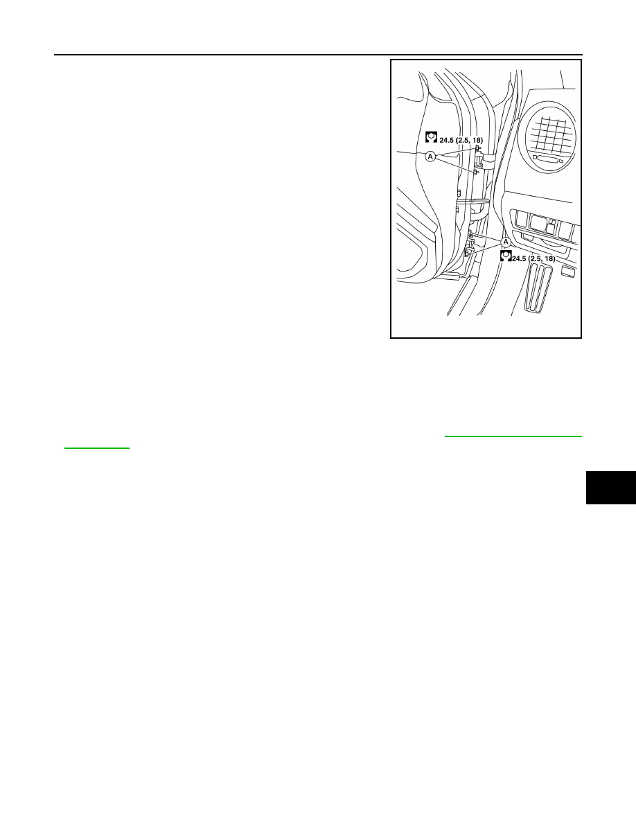
3. Remove front door hinge nuts (A) (door side) and the door

assembly.

INSTALLATION

Installation is in the reverse order of removal.

CAUTION:

• Check front door check link and hinge rotating point for poor lubrication. If necessary, apply a suit-

able multi-purpose grease.

• After installation, check front door open/close, lock/unlock operation.

• After installation, perform the front door adjustment procedure. Refer to 

DLK-215, "FRONT DOOR :

Adjustment"

.

• After adjusting, apply touch-up paint (body color) to the head of front door hinge bolts and nuts.

FRONT DOOR : Adjustment

INFOID:0000000009471769

ADJUSTMENT

ALKIA2793ZZ

DLK-216

< REMOVAL AND INSTALLATION >

DOOR

Check the clearance and surface height between front door and each part by visual inspection and tactile feel. 

If the clearance and the surface height are out of specification, adjust them according to the adjustment proce-

dure.

Unit: mm (in)

LONGITUDINAL CLEARANCE 

1. Confirm the rear door adjustments and adjust if necessary. Refer to 

DLK-218, "REAR DOOR : Adjust-

ment"

.

2. Remove the front fender. Refer to 

DLK-211, "Removal and Installation"

.

1.

Front fender

2.

Front door assembly

3.

Rear door assembly

AWKIA1339GB

Section

Item

Measurement

Standard

A-A

D

Clearance

4.25 

± 1.0 (0.17 ± 0.04)

E

Surface height

0.0 

± 1.0 (0.0 ± 0.04)

B-B

F

Clearance

4.25 

± 1.0 (0.17 ± 0.04)

G

Surface height

0.0 

± 1.0 (0.0 ± 0.04)

DOOR

DLK-217

< REMOVAL AND INSTALLATION >

C

D

E

F

G

H

I

J

L

M

A

B

DLK

N

O

P

3. Loosen the hinge bolts.
4. Raise or lower the front door assembly at rear edge to adjust until it is within specifications provided.
5. Tighten the hinge bolts.
6. Install the front fender. Refer to 

DLK-211, "Removal and Installation"

.

SURFACE HEIGHT ADJUSTMENT 

1. Loosen the front door hinge nuts.
2. Move the top and or bottom in or out as necessary until it is within specifications provided.
3. Tighten the hinge nuts to specifications.

REAR DOOR
REAR DOOR : Exploded View

INFOID:0000000009471770

REAR DOOR : Removal and Installation

INFOID:0000000009471771

CAUTION:

• Use two people when removing or installing the rear door assembly due to its heavy weight.

• When removing and installing rear door assembly, support rear door with a suitable tool.

REMOVAL

1. Pull out grommet and disconnect rear door harness connector.
2. Remove the check link bolt from the center pillar.

1.

Rear door assembly

2.

Rear door check link

3.

Rear door lower hinge

4.

Rear door upper hinge

Grease

ALKIA2794ZZ

DLK-218

< REMOVAL AND INSTALLATION >

DOOR

3. Remove rear door hinge nuts (a) (door side) and the door

assembly (1).

INSTALLATION

Installation is in the reverse order of removal.

CAUTION:

• Check rear door check link and hinge rotating point for poor lubrication. If necessary, apply a suit-

able multi-purpose grease.

• After installation, check rear door open/close, lock/unlock operation.

• After installation, perform the rear door adjustment procedure. Refer to 

DLK-218, "REAR DOOR :

Adjustment"

.

• After adjusting, apply touch-up paint (body color) to the head of rear door hinge bolts and nuts.

REAR DOOR : Adjustment

INFOID:0000000009471772

ADJUSTMENT

ALKIA0016GB


Content   ..  372  373  374  375   ..