Nissan Maxima. Manual - part 348
REMOTE KEYLESS ENTRY RECEIVER
DLK-111
< DTC/CIRCUIT DIAGNOSIS >
C
D
E
F
G
H
I
J
L
M
A
B
DLK
N
O
P
Is the inspection result normal?
YES
>> GO TO 7
NO
>> GO TO 2
2.
CHECK REMOTE KEYLESS ENTRY RECEIVER POWER SUPPLY
1. Disconnect remote keyless entry receiver connector.
2. Check voltage between remote keyless entry receiver connector and ground.
Is the inspection result normal?
YES
>> GO TO 4
NO
>> GO TO 3
3.
CHECK REMOTE KEYLESS ENTRY RECEIVER CIRCUIT 1
1. Disconnect BCM connector.
2. Check continuity between BCM connector and remote keyless
entry receiver connector.
3. Check continuity between BCM connector and ground.
Is the inspection result normal?
YES
>> Reconnect BCM, GO TO 4
NO
>> Repair or replace harness between BCM and remote keyless entry receiver.
Terminals
Condition
Signal
(Reference value)
(+)
(–)
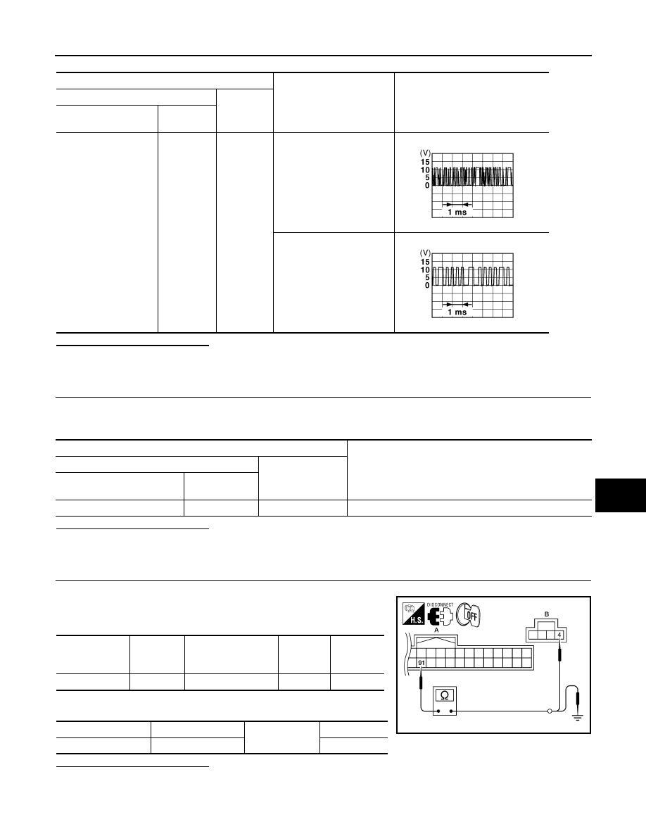
Remote keyless entry
receiver connector
Terminal
M27
2
Ground
Waiting
(All doors closed)
When signal is received
(All doors closed)
JMKIA0064GB
JMKIA0065GB
Terminals
Voltage
(Reference value)
(+)
(–)
Remote keyless entry receiver
connector
Terminal
M27
4
Ground
Battery
BCM connector
Terminal
Remote keyless entry
receiver
connector
Terminal
Continuity
A: M19
91
B: M27
4
Yes
BCM connector
Terminal
Ground
Continuity
A: M19
91
No
ALKIA1687ZZ