Nissan Maxima. Manual - part 240
BR-28
< REMOVAL AND INSTALLATION >
VACUUM LINES
VACUUM LINES
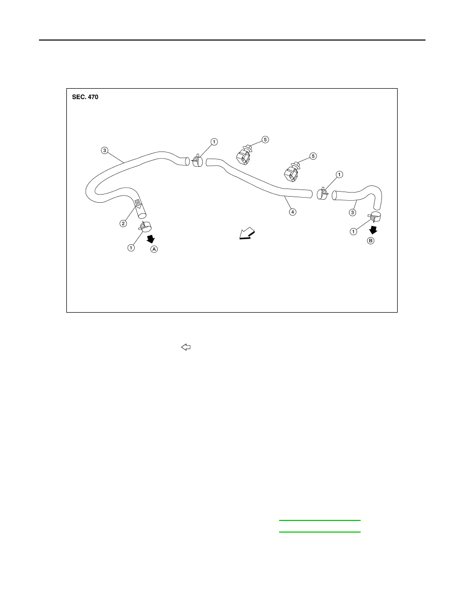
Exploded View
INFOID:0000000009466599
Removal and Installation
INFOID:0000000009466600
REMOVAL
1. Disconnect the vacuum hose from the brake booster.
2. Disconnect the vacuum hose from the intake manifold.
3. Release the clips and remove the vacuum pipe with the vacuum hoses attached.
4. Remove the vacuum hoses from the vacuum pipe.
INSPECTION AFTER REMOVAL
Visual Inspection
Check for correct installation, damage and deterioration of the vacuum hoses and pipe.
Valve Air-tightness Check
• Connect a suitable tool (hand vacuum pump) at each end of the vacuum hose to inspect the check valve
operation.
• Replace the vacuum hose component or check valve if out of specification.
INSTALLATION
Installation is in the reverse order of removal.
CAUTION:
1.
Clamp
2.
Installation arrow
3.
Vacuum hose
4.
Vacuum pipe
5.
Clip
A. To intake manifold
B. To brake booster
Front
AWFIA0436ZZ
Vacuum applied at booster end
: Refer to
Vacuum applied at intake manifold end
: Refer to