Nissan Maxima. Manual - part 235


  Index      Nissan     Nissan Maxima (2009-2014 year) - Service and Repair Manual


Search            


Content   ..  233  234  235  236   ..


Nissan Maxima. Manual - part 235


BR-8

< BASIC INSPECTION >

REAR DISC BRAKE

REAR DISC BRAKE

BRAKE PAD
BRAKE PAD : Inspection of Pad

INFOID:0000000009466577
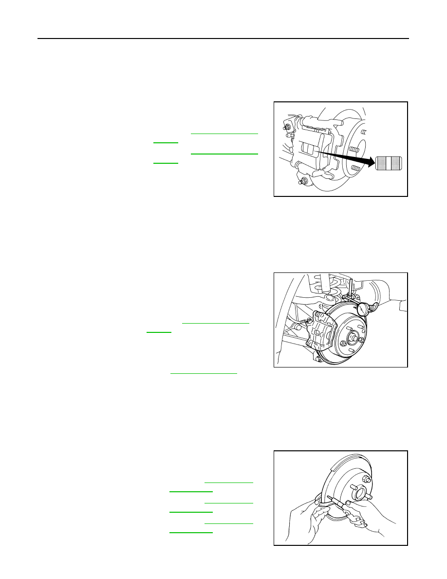
PAD WEAR

• Check pad thickness from the inspection hole on cylinder body.

Check using a scale if necessary.

DISC ROTOR
DISC ROTOR : Inspection of Rotor

INFOID:0000000009466578

VISUAL

Check surface of disc rotor for uneven wear, cracks, and serious damage. Replace if necessary.

RUNOUT

1. Attach disc rotor to wheel hub using wheel nuts (at two or more

positions). 

2. Inspect runout using dial gauge placed at 10 mm (0.39 in) inside

disc edge.

NOTE:

Before measuring, make sure that wheel bearing axial end play

is within the specification. Refer to 

RAX-5, "Inspection"

.

3. When runout exceeds limit value, displace mounting positions of disc rotor by one hole. Then find a posi-

tion of the minimum value for runout. 

4. If runout is outside the specified value after performing the above operation, refinish the disc rotor using

Tool.

THICKNESS

Check the thickness of the disc rotor using a micrometer. Replace

disc rotor if the thickness is less than the wear limit.

Standard thickness

: Refer to 

BR-46, "Rear Disc 

Brake"

.

Minimum thickness

: Refer to 

BR-46, "Rear Disc 

Brake"

.

ALFIA0155ZZ

Runout limit 

Refer to 

BR-46, "Rear Disc 

Brake"

.

(With it attached to the vehicle)

Tool number

: 38-PFM90.5

BRA0697D

Standard thickness

: Refer to 

BR-46, "Rear 

Disc Brake"

.

Minimum thickness

: Refer to 

BR-46, "Rear 

Disc Brake"

.

Thickness variation
(Measured at 8 positions)

: Refer to 

BR-46, "Rear 

Disc Brake"

.

SFIA2284E

BRAKE BOOSTER

BR-9

< BASIC INSPECTION >

C

D

E

G

H

I

J

K

L

M

A

B

BR

N

O

P

BRAKE BOOSTER

Inspection

INFOID:0000000009466579

OPERATION

With engine stopped, change vacuum to atmospheric pressure by

depressing brake pedal several times. Then with brake pedal fully

depressed, start engine and when vacuum pressure reaches the

standard, make sure that clearance between brake pedal and floor

panel decreases.

AIR TIGHT

• Run engine at idle for approximately 1 minute, and stop it after

applying vacuum to booster. Depress brake pedal normally to

change vacuum to atmospheric pressure. Make sure that distance

at intervals of 5 seconds between brake pedal and floor panel

gradually increases.

• Depress brake pedal while engine is running, and stop engine with pedal depressed. The pedal stroke

should not change after holding pedal down for 30 seconds.

BRA0037D

SBR365AA

BR-10

< BASIC INSPECTION >

VACUUM LINES

VACUUM LINES

Inspection

INFOID:0000000009466580

VISUAL INSPECTION

Check for improper assembly, damage and deterioration. Replace as necessary.

CHECK VALVE INSPECTION

Airtightness Inspection

Use a suitable tool to check the built-in check valve. Replace the

vacuum hose with the built-in check valve as an assembly if the vac-

uum hose is out of specification.

When suitable tool (A) is con-
nected to booster side (B)

Refer to 

BR-46, "Check 

Valve"

.

When suitable tool (A) is con-
nected to engine side (C)

Refer to 

BR-46, "Check 

Valve"

.

JPFIA0024ZZ

BRAKE MASTER CYLINDER

BR-11

< BASIC INSPECTION >

C

D

E

G

H

I

J

K

L

M

A

B

BR

N

O

P

BRAKE MASTER CYLINDER

Inspection

INFOID:0000000009466581

LEAK INSPECTION

Check for leaks at master cylinder to brake booster attachment point, reservoir tank, and brake tube connec-

tions.


Content   ..  233  234  235  236   ..