Nissan Maxima. Manual - part 171


  Index      Nissan     Nissan Maxima (2009-2014 year) - Service and Repair Manual


Search            


Content   ..  169  170  171  172   ..


Nissan Maxima. Manual - part 171


AV-504

< REMOVAL AND INSTALLATION >

[COLOR DISPLAY - W/ BOSE]

REAR VIEW CAMERA

REAR VIEW CAMERA

Removal and Installation

INFOID:0000000009471417

REMOVAL

1. Remove the license plate finisher. Refer to 

EXL-166, "Removal and Installation"

.

2. Remove trunk lid finisher. Refer to 

INT-36, "Exploded View"

.

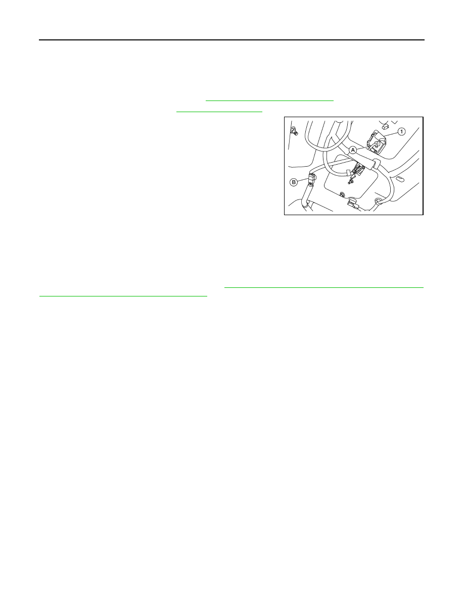
3. Disconnect the rear view camera connector (B), press the rear

view camera tab (A) and remove the rear view camera (1).

INSTALLATION

Installation is in the reverse order of removal.

Adjustment

INFOID:0000000009471418

REAR VIEW CAMERA

For adjustment on the rear view camera, refer to 

DLK-12, "ADDITIONAL SERVICE WHEN REPLACING

CONTROL UNIT : Special Repair Requirement"

.

ALNIA1156ZZ

AV

DIAGNOSIS AND REPAIR WORKFLOW

AV-505

< BASIC INSPECTION >

[COLOR DISPLAY - W/BOSE & NAVI]

C

D

E

F

G

H

I

J

K

L

M

B

A

O

P

BASIC INSPECTION

DIAGNOSIS AND REPAIR WORKFLOW

Work Flow

INFOID:0000000009471419

OVERALL SEQUENCE

• Reference 1··· Refer to 

AV-536, "CONSULT Function (MULTI AV)"

.

• Reference 2··· Refer to 

AV-635, "Symptom Table"

.

DETAILED FLOW

1.

CHECK SYMPTOM

Check the malfunction symptoms by performing the following items. 

• Interview the customer to obtain the malfunction information (conditions and environment when the malfunc-

tion occurred).

• Check the symptom. 

>> GO TO 2.

2.

SELF-DIAGNOSIS (CONSULT)

1. Connect CONSULT and perform “SELF-DIAGNOSIS” for “MULTI AV”.

NOTE:

Skip to step 4 of the diagnosis procedure if “MULTI AV” is not displayed.

2. Check if any DTC No. is displayed in the self-diagnosis results.

AWNIA2486GB

AV-506

< BASIC INSPECTION >

[COLOR DISPLAY - W/BOSE & NAVI]

DIAGNOSIS AND REPAIR WORKFLOW

Is any DTC No. displayed?

YES

>> GO TO 3.

NO

>> GO TO 4.

3.

CHECK SELF-DIAGNOSIS RESULTS (CONSULT)

1. Check the DTC No. indicated in the self-diagnosis results.

2. Perform the relevant diagnosis referring to the DTC No. list. Refer to 

AV-607, "DTC Index"

.

NOTE:

Start with the diagnosis for the CAN communication system if “CAN COMM CIRCUIT [U1000] or CONTROL

UNIT (CAN) [U1010]” is displayed.

>> GO TO 5.

4.

PERFORM DIAGNOSIS BY SYMPTOM

Perform the relevant diagnosis referring to the diagnosis chart by symptom. Refer to 

AV-635, "Symptom

Table"

.

>> GO TO 5.

5.

REPAIR OR REPLACE MALFUNCTIONING PARTS

Repair or replace the identified malfunctioning parts.

NOTE:

Erase the stored self-diagnosis results after repairing or replacing the relevant components if any DTC No. has

been indicated in the self-diagnosis results. 

>> GO TO 6.

6.

CHECK AFTER REPAIR

1. Perform self-diagnosis for “MULTI AV” with CONSULT after repairing or replacing the malfunctioning

parts.

2. Check if any DTC No. is displayed in the self-diagnosis results.
Is any DTC No. displayed?

YES

>> GO TO 3.

NO

>> GO TO 7.

7.

FINAL CHECK

Perform the operation check to confirm that the malfunction symptom is solved or that any other symptoms

are present.
Are any symptoms present?

YES

>> GO TO 4.

NO

>> Inspection End.

AV

INSPECTION AND ADJUSTMENT

AV-507

< BASIC INSPECTION >

[COLOR DISPLAY - W/BOSE & NAVI]

C

D

E

F

G

H

I

J

K

L

M

B

A

O

P

INSPECTION AND ADJUSTMENT

ADDITIONAL SERVICE WHEN REPLACING CONTROL UNIT
ADDITIONAL SERVICE WHEN REPLACING CONTROL UNIT : Description

INFOID:0000000009471420

BEFORE REPLACEMENT

When replacing AV control unit, save current vehicle specification with CONSULT configuration before

replacement.

AFTER REPLACEMENT

CAUTION:

When replacing AV control unit, you must perform “WRITE CONFIGURATION” with CONSULT.

• Complete the procedure of “WRITE CONFIGURATION” in order.

• If you set incorrect “WRITE CONFIGURATION”, incidents might occur.

• Configuration is different for each vehicle model. Confirm configuration of each vehicle model.

ADDITIONAL SERVICE WHEN REPLACING CONTROL UNIT : Special Repair Re-
quirement

INFOID:0000000009471421

1.

SAVING VEHICLE SPECIFICATION

-CONSULT Configuration

Perform “READ CONFIGURATION” to save current vehicle specification. Refer to 

AV-507, "CONFIGURA-

TION (AV CONTROL UNIT) : Description"

.

NOTE:

If “READ CONFIGURATION” can not be used, use the “WRITE CONFIGURATION - Manual selection”.

>> GO TO 2.

2.

REPLACE AV CONTROL UNIT

Replace AV control unit. Refer to 

AV-652, "Removal and Installation"

.

>> GO TO 3.

3.

WRITING VEHICLE SPECIFICATION

-CONSULT Configuration

Perform “WRITE CONFIGURATION - Config file” or “WRITE CONFIGURATION - Manual selection” to write

vehicle specification. Refer to 

AV-508, "CONFIGURATION (AV CONTROL UNIT) : Special Repair Require-

ment"

.

>> GO TO 4.

4.

OPERATION CHECK

Check that the operation of the AV control unit and camera images (fixed guide lines and predictive course

lines) are normal.

>> WORK END

CONFIGURATION (AV CONTROL UNIT)
CONFIGURATION (AV CONTROL UNIT) : Description

INFOID:0000000009471422

• Since vehicle specifications are not included in the AV control unit after replacement, it is required to write

vehicle specifications with CONSULT.

• Configuration has three functions as follows.


Content   ..  169  170  171  172   ..