Content .. 1139 1140 1141 1142 ..
Nissan Maxima. Manual - part 1141
TM-28
< SYSTEM DESCRIPTION >
[CVT: RE0F09B]
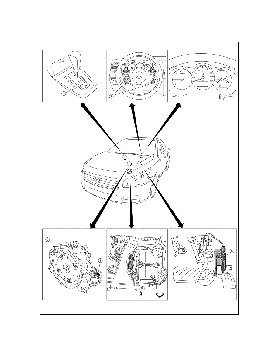
LOCK-UP AND SELECT CONTROL SYSTEM
Component Parts Location
INFOID:0000000009469032
AWDIA0564ZZ
|
|
|
Content .. 1139 1140 1141 1142 ..
TM-28 < SYSTEM DESCRIPTION > [CVT: RE0F09B] LOCK-UP AND SELECT CONTROL SYSTEM Component Parts Location INFOID:0000000009469032 AWDIA0564ZZ |