Nissan Maxima. Manual - part 1129


  Index      Nissan     Nissan Maxima (2009-2014 year) - Service and Repair Manual


Search            


Content   ..  1127  1128  1129  1130   ..


Nissan Maxima. Manual - part 1129


STC-22

< UNIT REMOVAL AND INSTALLATION >

EPS CONTROL UNIT

UNIT REMOVAL AND INSTALLATION

EPS CONTROL UNIT

Removal and Installation

INFOID:0000000009466568

REMOVAL

1. Disconnect negative battery terminal. Refer to 

PG-67, "Removal and Installation (Battery)"

.

2. Remove audio display unit. Refer to 

AV-73, "Removal and Installation"

 (BASE AUDIO), 

AV-161, "Removal

and Installation"

 (BOSE W/MONOCHROME DISPLAY), 

AV-481, "Removal and Installation"

 (BOSE W/

COLOR DISPLAY), 

AV-652, "Removal and Installation"

 (BOSE W/COLOR DISPLAY W/NAVIGATION).

3. Remove automatic drive position control unit (if equipped). Refer to 

ADP-170, "Removal and Installation"

.

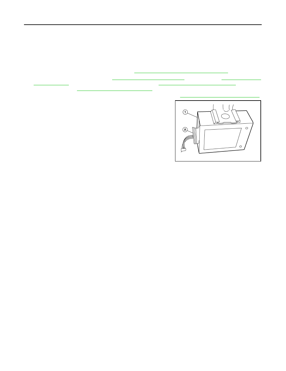
4. Remove EPS control unit (1) from the bracket.
5. Disconnect EPS control unit harness connector (A) and remove

the EPS control unit (1).

INSTALLATION

Installation is in the reverse order of removal.

ALGIA0040ZZ

STR-1

ENGINE

C

D

E

F

G

H

I

J

K

L

M

SECTION 

STR

A

STR

N

O

P

CONTENTS

STARTING SYSTEM

VQ35DE

BASIC INSPECTION  ....................................

2

DIAGNOSIS AND REPAIR WORKFLOW  ..........

2

Work Flow (With GR8-1200 NI)  ................................

2

Work Flow (Without GR8-1200 NI)  ...........................

6

SYSTEM DESCRIPTION  ..............................

8

STARTING SYSTEM ...........................................

8

System Diagram ........................................................

8

System Description  ...................................................

8

Component Description ............................................

8

DTC/CIRCUIT DIAGNOSIS  ..........................

9

B TERMINAL CIRCUIT  .......................................

9

Description ................................................................

9

Diagnosis Procedure .................................................

9

S CONNECTOR CIRCUIT ..................................

11

Description ..............................................................

11

Diagnosis Procedure ...............................................

11

WIRING DIAGRAM ......................................

12

STARTING SYSTEM ..........................................

12

Wiring Diagram  .......................................................

12

SYMPTOM DIAGNOSIS  ..............................

16

STARTING SYSTEM .........................................

16

Symptom Table  .......................................................

16

PRECAUTION ..............................................

17

PRECAUTIONS .................................................

17

Precaution for Supplemental Restraint System 
(SRS) "AIR BAG" and "SEAT BELT PRE-TEN-
SIONER" .................................................................

17

PREPARATION ...........................................

18

PREPARATION .................................................

18

Special Service Tool ................................................

18

Commercial Service Tools .......................................

18

REMOVAL AND INSTALLATION ...............

19

STARTER MOTOR  ...........................................

19

Removal and Installation  .........................................

19

SERVICE DATA AND SPECIFICATIONS 
(SDS) ............................................................

20

STARTER MOTOR  ...........................................

20

Starter ......................................................................

20

STR-2

< BASIC INSPECTION >

[VQ35DE]

DIAGNOSIS AND REPAIR WORKFLOW

BASIC INSPECTION

DIAGNOSIS AND REPAIR WORKFLOW

Work Flow (With GR8-1200 NI)

INFOID:0000000009464997

STARTING SYSTEM DIAGNOSIS WITH GR8-1200 NI

To test the starting system, use the following special service tool:

• GR8-1200 NI Multitasking battery and electrical diagnostic station

NOTE:

Refer to the diagnostic station Instruction Manual for proper starting system diagnosis procedures.

DIAGNOSIS AND REPAIR WORKFLOW

STR-3

< BASIC INSPECTION >

[VQ35DE]

C

D

E

F

G

H

I

J

K

L

M

A

STR

N

P

O

OVERALL SEQUENCE

DETAILED FLOW

NOTE:

To ensure a complete and thorough diagnosis, the battery, starter motor and generator test segments must be

done as a set from start to finish.

1.

DIAGNOSIS WITH MULTITASKING BATTERY AND ELECTRICAL DIAGNOSTIC STATION GR8-1200 NI

AWBIA1200GB


Content   ..  1127  1128  1129  1130   ..