Content .. 1124 1125 1126 1127 ..
Nissan Maxima. Manual - part 1126
STC-10
< DTC/CIRCUIT DIAGNOSIS >
ENGINE SPEED SIGNAL CIRCUIT
ENGINE SPEED SIGNAL CIRCUIT
Description
INFOID:0000000009466557
ECM sends engine speed signal to power steering control unit.
Diagnosis Procedure
INFOID:0000000009466558
Regarding Wiring Diagram information, refer to
.
1.
PERFORM ECM SELF-DIAGNOSIS
With CONSULT
Perform ECM self-diagnosis.
Is any error system detected?
YES
>> Check the error system.
NO
>> GO TO 2.
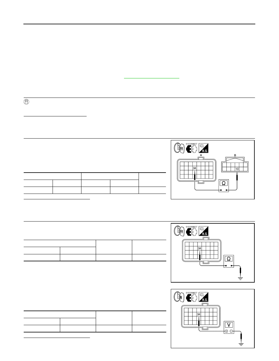
2.
CHECK HARNESS BETWEEN ECM AND POWER STEERING CONTROL UNIT FOR OPEN
1. Turn the ignition switch OFF.
2. Disconnect ECM connector E10.
3. Disconnect power steering control unit connector.
4. Check continuity between ECM connector E10 (A) terminal 94
and power steering control unit connector M59 (B) terminal 10.
Is the inspection result normal?
YES
>> GO TO 3.
NO
>> Repair harness or connectors.
3.
CHECK HARNESS BETWEEN ECM AND POWER STEERING CONTROL UNIT FOR SHORT
1. Check continuity between ECM connector E10 terminal 94 and
ground.
2. Turn ignition switch ON.
3. Check voltage between ECM connector E10 terminal 94 and
ground.
Is the inspection result normal?
YES
>> GO TO 4.
ECM
Power steering control unit
Continuity
Connector
Terminal
Connector
Terminal
E10 (A)
94
M59 (B)
10
Yes
AWGIA0039ZZ
ECM
Ground
Continuity
Connector
Terminal
E10
94
—
No
AWGIA0095ZZ
ECM
Ground
Voltage (Approx.)
Connector
Terminal
E10
94
—
0V
AWGIA0096ZZ