Content .. 1073 1074 1075 1076 ..
Nissan Maxima. Manual - part 1075
IPDM E/R (INTELLIGENT POWER DISTRIBUTION MODULE ENGINE ROOM)
SEC-125
< ECU DIAGNOSIS INFORMATION >
C
D
E
F
G
H
I
J
L
M
A
B
SEC
N
O
P
Fail Safe
INFOID:0000000010068753
CAN COMMUNICATION CONTROL
When CAN communication with ECM and BCM is impossible, IPDM E/R performs fail-safe control. After CAN
communication recovers normally, it also returns to normal control.
If No CAN Communication Is Available With ECM
If No CAN Communication Is Available With BCM
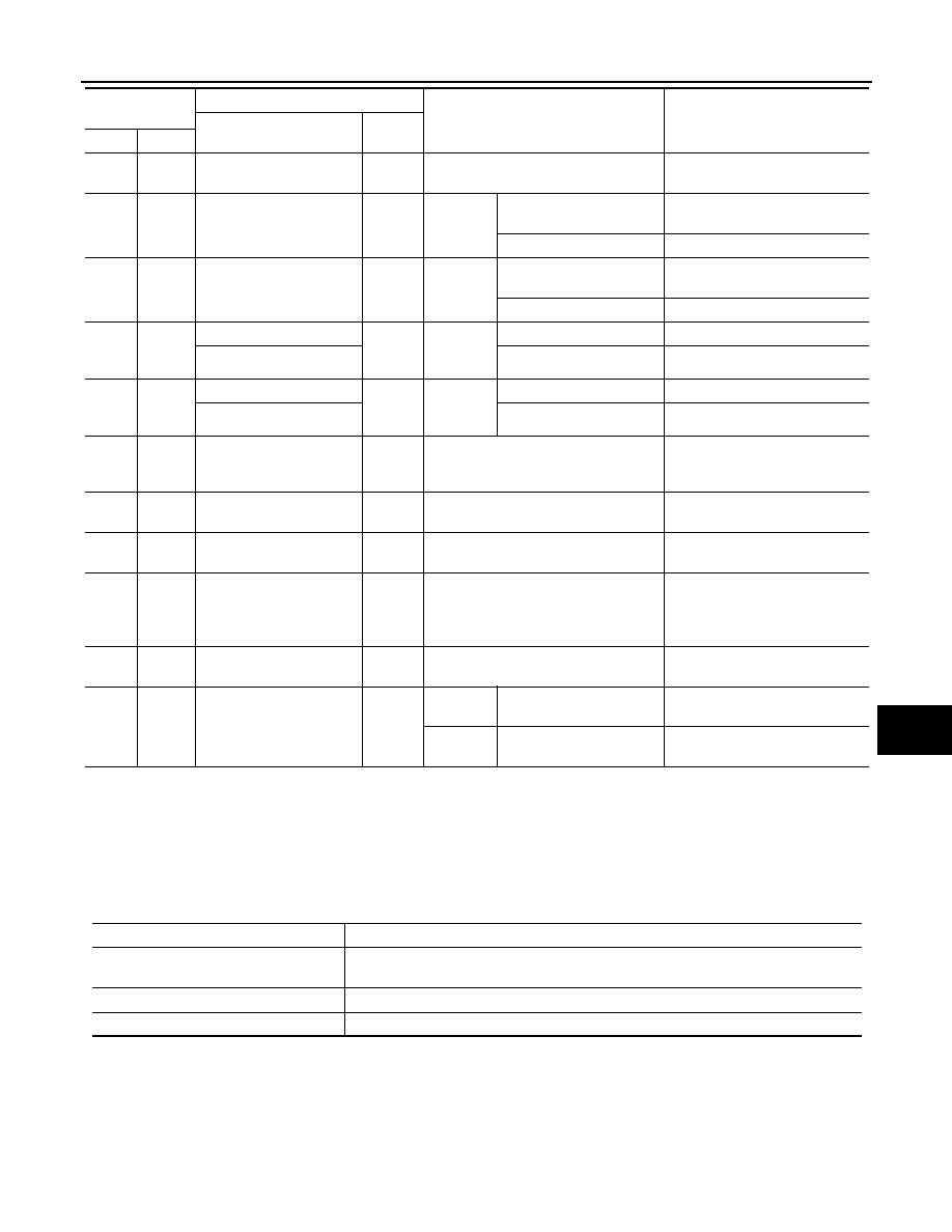
88
(R/W)
Ground
Washer pump power sup-
ply
Output
Ignition switch ON
Battery voltage
89
(L/W)
Ground Headlamp HI (RH)
Output
Ignition
switch ON
• Lighting switch HI
• Lighting switch PASS
Battery voltage
Lighting switch OFF
0 V
90
(G)
Ground Headlamp HI (LH)
Output
Ignition
switch ON
• Lighting switch HI
• Lighting switch PASS
Battery voltage
Lighting switch OFF
0 V
91
(LG/
R)
Ground
Parking lamp (RH)
Output
Ignition
switch ON
Lighting switch 1ST
Battery voltage
Side marker lamp (RH)
Lighting switch OFF
0 V
92
(LG/
B)
Ground
Parking lamp (LH)
Output
Ignition
switch ON
Lighting switch 1ST
Battery voltage
Side marker lamp (LH)
Lighting switch OFF
0 V
99
(BR/
W)
Ground Ambient sensor ground
—
Ignition switch ON
0V
100
(SB)
Ground Ambient sensor
—
Ignition switch ON
5V
101
(W)
Ground
Refrigerant pressure sen-
sor ground
—
Ignition switch ON
0V
102
(R)
Ground
Refrigerant pressure sen-
sor
—
• Ignition switch ON (READY)
• Both A/C switch and blower motor
switch ON (electric compressor oper-
ates)
1.0 - 4.0V
103
(P)
Ground
Refrigerant pressure sen-
sor power supply
—
Ignition switch ON
5V
105
(V)
Ground
Daytime light relay control
(Only for Canada models)
Output
Ignition
switch ON
Daytime light system ac-
tive
Battery voltage
Ignition
switch ON
Daytime light system inac-
tive
0 V
Terminal No.
(Wire color)
Description
Condition
Value
(Approx.)
Signal name
Input/
Output
+
−
Control part
Fail-safe in operation
Cooling fan
• Signals cooling fans ON when the ignition switch is turned ON
• Signals cooling fans OFF when the ignition switch is turned OFF
A/C compressor
A/C relay OFF
Generator
Outputs the power generation command signal (PWM signal) 0%