Nissan Maxima. Manual - part 106
AV-244
< DTC/CIRCUIT DIAGNOSIS >
[COLOR DISPLAY - W/O BOSE]
HORIZONTAL SYNCHRONIZING (HP) SIGNAL CIRCUIT
HORIZONTAL SYNCHRONIZING (HP) SIGNAL CIRCUIT
Description
INFOID:0000000010064891
In composite image (AUX image, camera image), transmit the vertical synchronizing (VP) signal and horizon-
tal synchronizing (HP) signal from display unit to AV control unit so as to synchronize the RGB images dis-
played with AV control unit such as the image quality adjusting menu, etc.
Diagnosis Procedure
INFOID:0000000010064892
Regarding Wiring Diagram information, refer to
AV-282, "Wiring Diagram - Without BOSE Audio System With-
1.
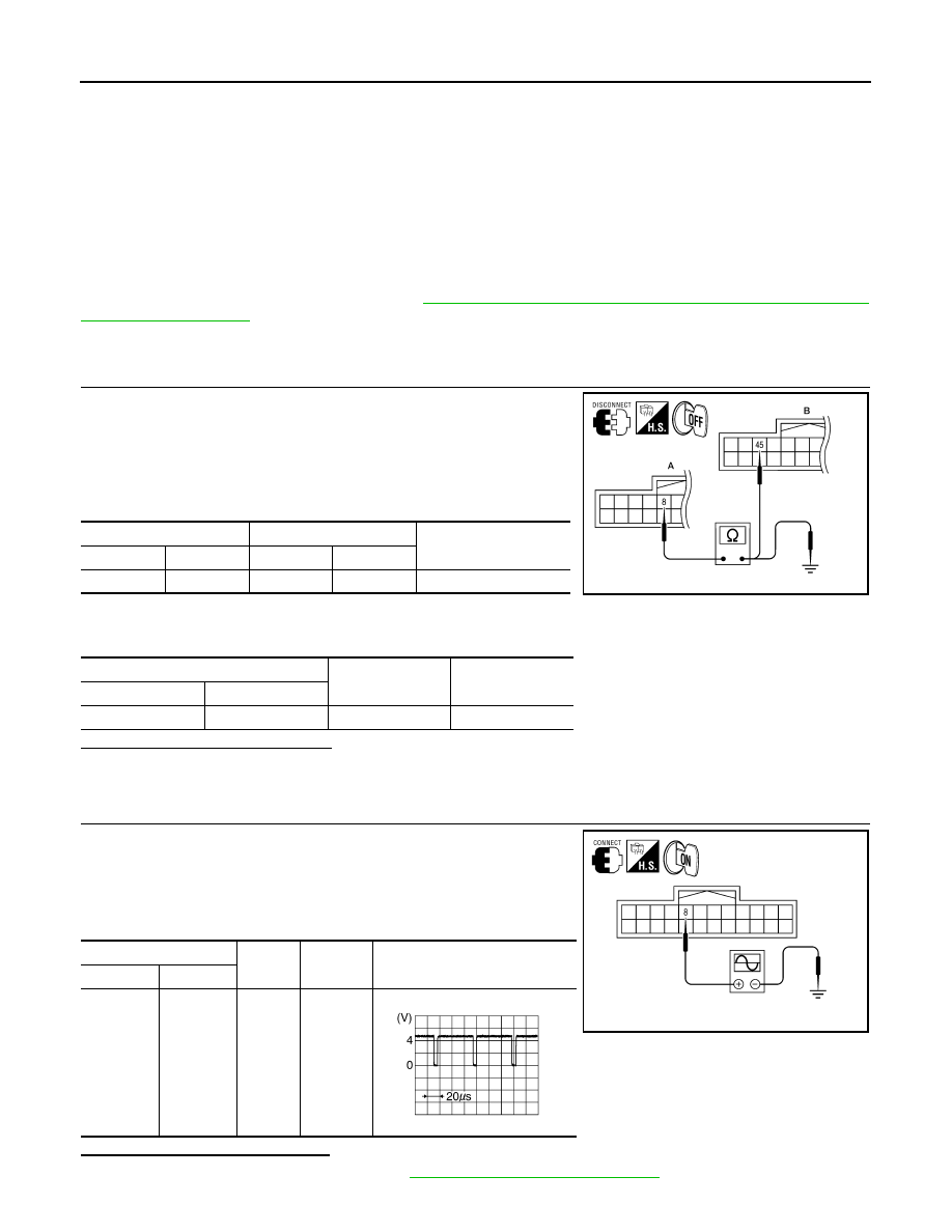
CHECK CONTINUITY HORIZONTAL SYNCHRONIZING (HP) SIGNAL CIRCUIT
1. Turn ignition switch OFF.
2. Disconnect display unit connector M141 and AV control unit con-
nector M117.
3. Check continuity between display unit harness connector M141
(A) terminal 8 and AV control unit harness connector M117 (B)
terminal 45.
4. Check continuity between display unit harness connector M141
(A) terminal 8 and ground.
Are continuity results as specified?
YES
>> GO TO 2.
NO
>> Repair harness or connector.
2.
CHECK HORIZONTAL SYNCHRONIZING (HP) SIGNAL
1. Connect display unit connector M141 and AV control unit con-
nector M117.
2. Turn ignition switch ON.
3. Check signal between display unit harness connector M141 ter-
minal 8 and ground.
Are voltage readings as specified?
YES
>> Replace AV control unit. Refer to
AV-311, "Removal and Installation"
A
B
Continuity
Connector
Terminal
Connector
Terminal
M141
8
M117
45
Yes
A
—
Continuity
Connector
Terminal
M141
8
Ground
No
ALNIA0394GB
(+)
(-)
Condition
Reference signal
Connector
Terminal
M141
8
Ground
Receive
audio sig-
nal
ALNIA0396GB
SKIB3601E