Nissan Maxima. Manual - part 55
AV-40
< DTC/CIRCUIT DIAGNOSIS >
[MONOCHROME DISPLAY - W/O BOSE]
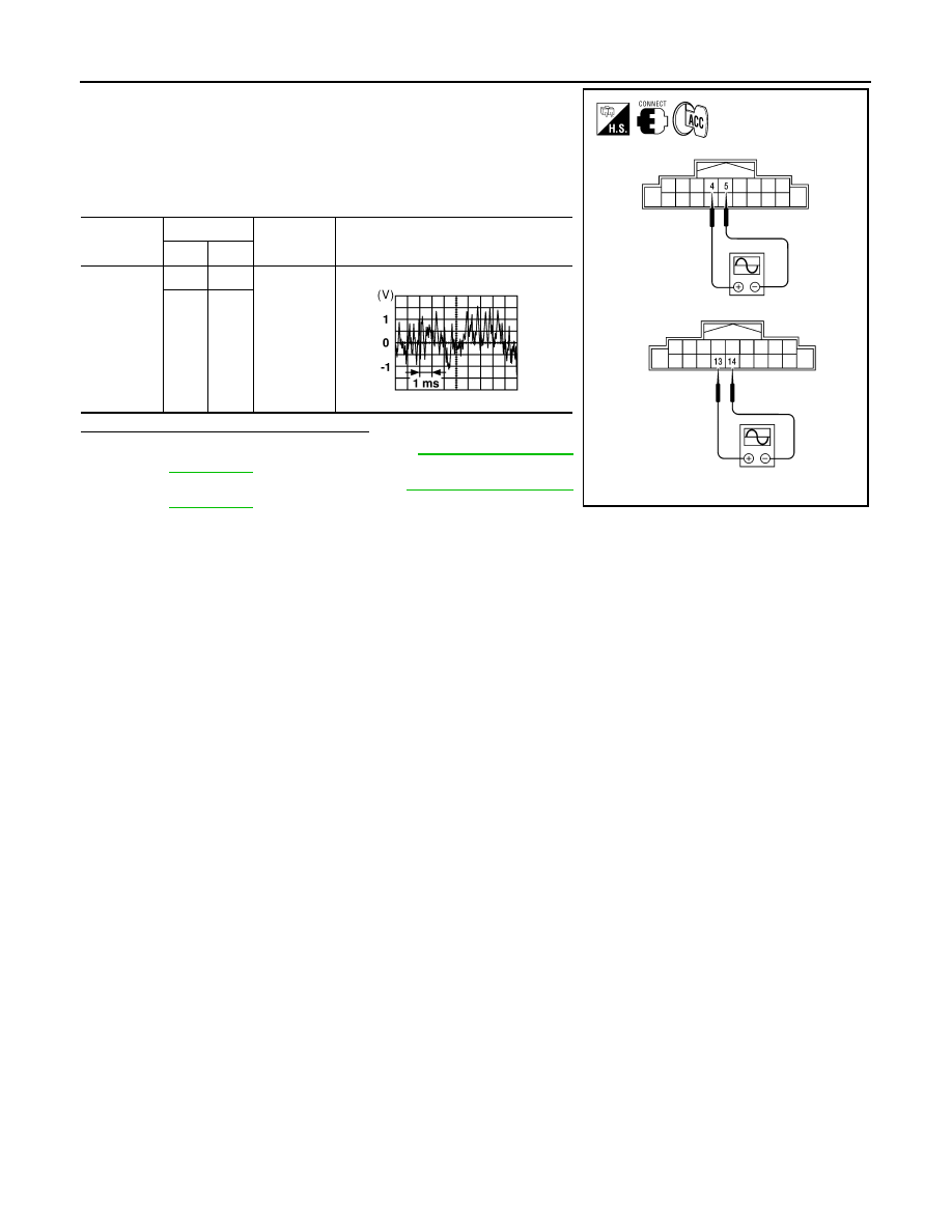
SUBWOOFER
1. Connect audio unit connector M133 and subwoofer amp. con-
nector B21.
2. Turn ignition switch to ACC.
3. Push “POWER” switch.
4. Check the signal between audio unit harness connector M133
terminals with CONSULT or oscilloscope.
Is the audio signal voltage as specified?
YES
>> Replace subwoofer amp. Refer to
NO
>> Replace audio unit. Refer to
Connector
Terminals
Condition
Reference
signal
(+)
(-)
M133
4
5
Receive
audio sig-
nal
13
14
AWNIA0034ZZ
SKIA0177E