Nissan Maxima. Manual - part 14
ADP-48
< DTC/CIRCUIT DIAGNOSIS >
POWER SUPPLY AND GROUND CIRCUIT
Regarding Wiring Diagram information, refer to
1.
CHECK POWER SUPPLY CIRCUIT
1. Turn ignition switch OFF.
2. Disconnect driver seat control unit.
3. Check voltage between driver seat control unit harness connector and ground.
Is the inspection result normal?
YES
>> GO TO 2
NO
>> Check the following.
• Repair or replace harness.
• Circuit breaker.
2.
CHECK GROUND CIRCUIT
Check continuity between the driver seat control unit harness connector and ground.
Is the inspection result normal?
YES
>> Driver seat control unit power supply and ground circuit are OK.
NO
>> Repair or replace harness.
DRIVER SEAT CONTROL UNIT : Special Repair Requirement
INFOID:0000000010051728
1.
PERFORM ADDITIONAL SERVICE
Perform additional service when removing battery negative terminal.
>> Refer to Owner’s Manual.
AUTOMATIC DRIVE POSITIONER CONTROL UNIT
AUTOMATIC DRIVE POSITIONER CONTROL UNIT : Diagnosis Procedure
INFOID:0000000010051729
NOTE:
Do not disconnect the battery negative terminal and the driver seat control unit connector until DTC is con-
firmed with CONSULT.
Regarding Wiring Diagram information, refer to
1.
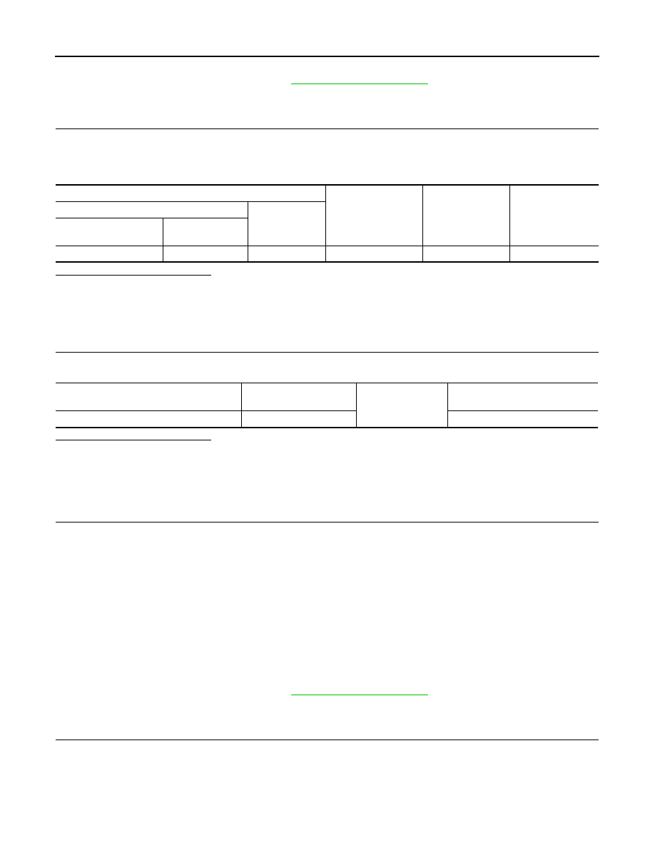
CHECK POWER SUPPLY CIRCUIT
Terminals
Power source
Condition
Voltage (V)
(Approx.)
(+)
(–)
Driver seat control unit
connector
Terminal
B211
37
Ground
Battery power supply
Ignition switch OFF
Battery voltage
Driver seat control unit
connector
Terminal
Ground
Continuity
B211
39
Yes