Nissan Altima HL32 Hybrid. Manual - part 834
MWI
IPDM E/R (INTELLIGENT POWER DISTRIBUTION MODULE ENGINE ROOM)
MWI-123
< ECU DIAGNOSIS >
C
D
E
F
G
H
I
J
K
L
M
B
A
O
P
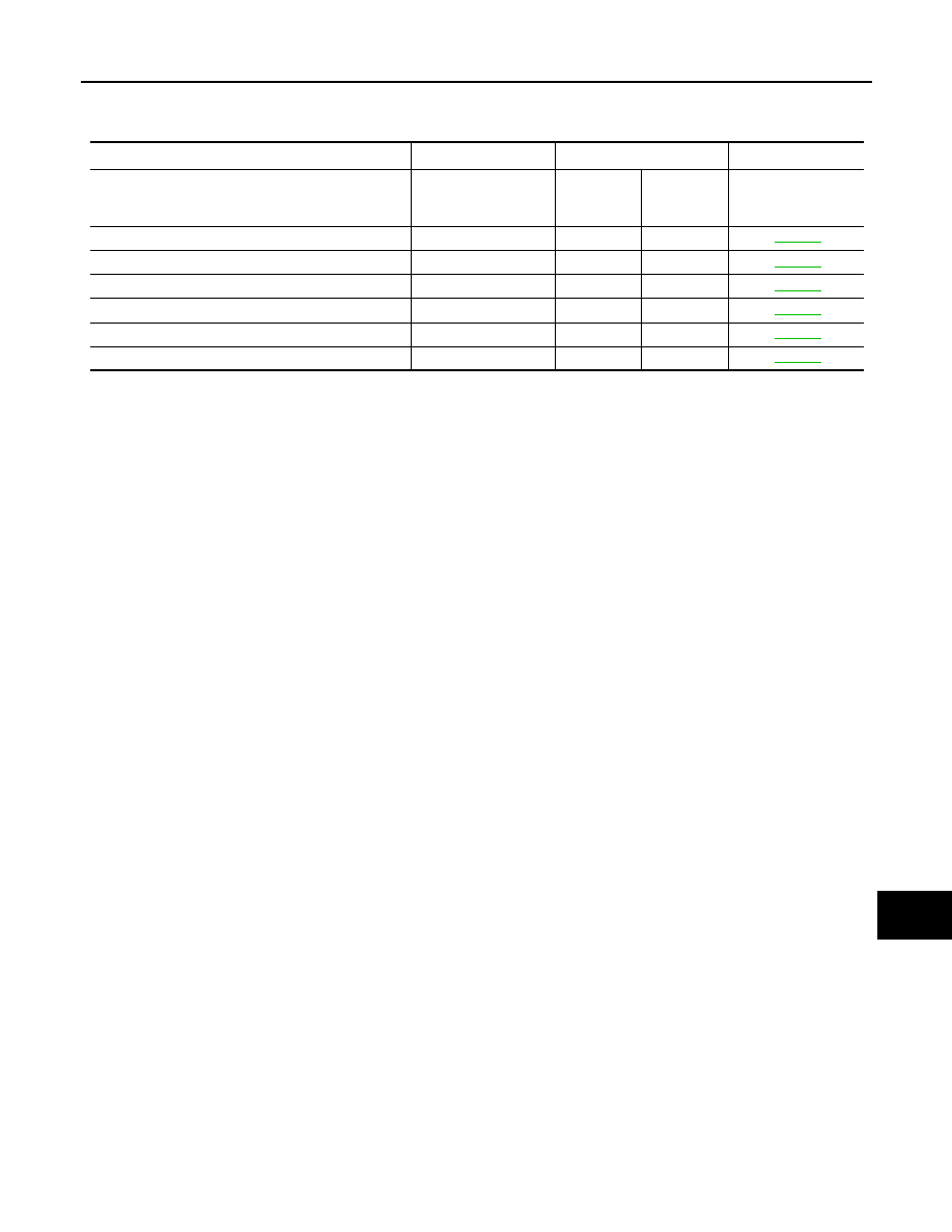
DTC Index
INFOID:0000000004501266
NOTE:
The details of TIME display are as follows.
• CRNT: The malfunctions that are detected now
• 1 - 39: The number is indicated when it is normal at present and a malfunction was detected in the past. It
increases like 0
→ 1 → 2 ··· 38 → 39 after returning to the normal condition whenever IGN OFF → ON. It is
fixed to 39 until the self-diagnosis results are erased if it is over 39. It returns to 0 when a malfunction is
detected again in the process.
CONSULT-III display
Fail-safe
TIME
NOTE
Refer to
No DTC is detected.
further testing
may be required.
—
—
—
—
U1000: CAN COMM CIRCUIT
×
CRNT
1 – 39
B2098: IGN RELAY ON
×
CRNT
1 – 39
B2099: IGN RELAY OFF
—
CRNT
1 – 39
B2108: STRG LCK RELAY ON
—
CRNT
1 – 39
B2109: STRG LCK RELAY OFF
—
CRNT
1 – 39
B210A: STRG LCK STATE SW
—
CRNT
1 – 39