Nissan Altima HL32 Hybrid. Manual - part 794


  Index      Nissan     Nissan Altima HL32 Hybrid (2009 year) - Service and Repair Manual


Search            


Content   ..  792  793  794  795   ..


Nissan Altima HL32 Hybrid. Manual - part 794


MA-12

< ON-VEHICLE MAINTENANCE >

ENGINE MAINTENANCE

ENGINE MAINTENANCE

DRIVE BELTS
DRIVE BELTS : Checking Drive Belts

INFOID:0000000004219646

WARNING:

Inspect the drive belt only when the Hybrid System is off.

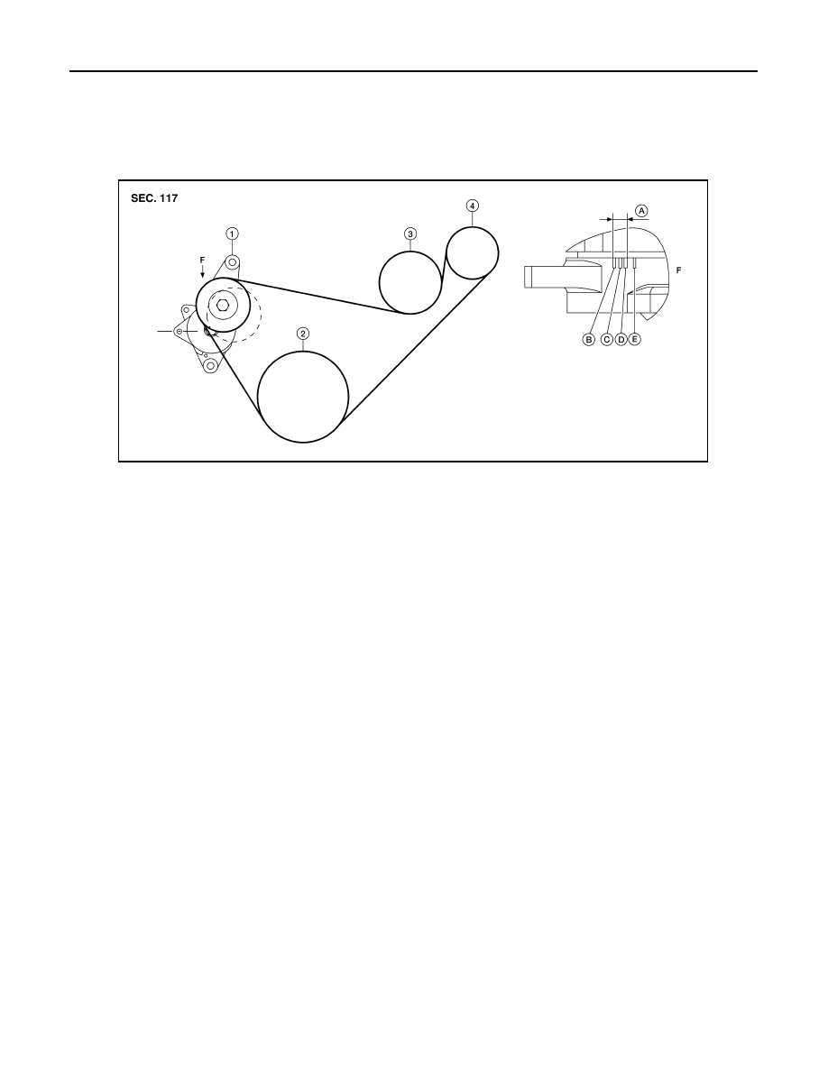
• Make sure that the stamp mark of drive belt auto-tensioner is within the usable range. 

NOTE:

• Check the drive belt auto-tensioner indicator (notch) when the engine is cold.

• When the new drive belt is installed, the range should be (A) as shown.

• Visually check entire belt for wear, damage or cracks.

• If the indicator is out of allowable use range or belt is damaged, replace the belt.

DRIVE BELTS : Tension Adjustment

INFOID:0000000004219647

• Belt tension is not manually adjustable, it is automatically adjusted by the drive belt auto-tensioner.

ENGINE COOLANT
ENGINE COOLANT : Changing Engine Coolant

INFOID:0000000004219648

WARNING:

• To avoid being scalded, never change the coolant when the engine and inverter are hot.

• Wrap a thick cloth around cap and carefully remove the cap. First, turn the cap a quarter of a turn to

release built-up pressure. Then push down and turn the cap all the way to remove.

DRAINING ENGINE COOLANT

1. Remove the engine undercover using power tool.
2. Open the radiator drain plug at the bottom of the radiator, and remove the radiator filler cap. This is the

only step required when partially draining the cooling system (radiator only). 

CAUTION:

Do not to allow the coolant to contact the drive belts. 

1.

Drive belt auto-tensioner 

2.

Crankshaft

3.

Water pump

4.

Idler pulley

A.

Water pump belt working range B.

Minimum belt length

C.

Nominal position

D.

Maximum belt length

E.

Maximum belt length +0.8%

F.

View F

AWBIA0586ZZ

ENGINE MAINTENANCE

MA-13

< ON-VEHICLE MAINTENANCE >

C

D

E

F

G

H

I

J

K

L

M

B

MA

N

O

A

3. Follow this step for heater core removal/replacement only. Disconnect the upper heater hose at the

engine side and apply moderate air pressure [103.46 kPa (15 psi, 1.055 kg/cm

2

) maximum air pressure]

into the hose for 30 seconds to blow the excess coolant out of the heater core.

4. When draining all of the coolant in the system, remove the reservoir tank and drain the coolant, then clean

the reservoir tank before installation.

5. When draining all of the coolant in the system for engine

removal or repair, open the drain plug on the cylinder block.

6. Check the drained coolant for contaminants such as rust, corrosion or discoloration.

If the coolant is contaminated, flush the engine cooling system.

REFILLING ENGINE COOLANT

1. Install the radiator drain plug. Install the reservoir tank and cylinder block drain plug, if removed for a total

system drain or for engine removal or repair.

• The radiator must be completely empty of coolant and water.

• Apply sealant to the threads of the cylinder block drain plugs. Use Genuine High Performance

Thread Sealant or equivalent. Refer to 

GI-15, "Recommended Chemical Products and Sealants"

 .

2. If disconnected, reattach the upper radiator hose at the engine side.
3. Set the vehicle heater controls to the full HOT and heater ON position. Push the ignition swtch twice to the

ON position with the Hybrid system and engine OFF as necessary to activate the heater mode.

4. Install the Tool by installing the radiator cap adapter (E) onto the

radiator tee opening (F). Then attach the gauge body assembly

(B) with the refill hose (D) and the venturi assembly (A) to the

radiator cap adapter.

• A: Venturi assembly 

• B: Guage body assembly

• C: Ball valve 

• D: Refill hose

• E: Radiator cap adapter

• F: Radiator tee

5. Insert the refill hose (D) into the coolant mixture container that is

placed at floor level. Make sure the ball valve (C) is in the closed

position. 

• Use Genuine NISSAN Long Life Anti-freeze coolant or

equivalent, mixed 50/50 with distilled water or demineral-

ized water.

Refer to 

MA-10, "Engine Oil Recommendation"

.

6. Install an air hose to the venturi assembly (A), the air pressure

must be within specification. 

KBIA0163E

Radiator drain plug

: Refer to 

CO-14, "Removal and Installation"

 .

Cylinder block drain plug

: Refer to 

EM-75, "Disassembly and Assembly"

 .

Tool number

: KV991J0070 (J-45695)

Engine coolant capacity 
(with reservoir tank)

: Refer to 

MA-10, "Fluids 

and Lubricants"

.

AWBIA0074GB

MA-14

< ON-VEHICLE MAINTENANCE >

ENGINE MAINTENANCE

CAUTION:

The compressed air supply must be equipped with an air dryer.

7. The vacuum gauge will begin to rise and there will be an audible hissing noise. During this process open

the ball valve (C) on the refill hose (D) slightly. Coolant will be visible rising in the refill hose (D). Once the

refill hose (D) is full of coolant, close the ball valve (C). This will purge any air trapped in the refill hose.

8. Continue to draw the vacuum until the gauge reaches 28 inches

of vacuum. The gauge may not reach 28 inches in high altitude

locations, follow the the vacuum specifications based on the alti-

tude above sea level as shown.

9. When the vacuum gauge has reached the specified amount, disconnect the air hose and wait 20 seconds

to see if the system loses any vacuum. If the vacuum level drops, perform any necessary repairs to the

system and repeat steps 6 - 8 to bring the vacuum to the specified amount. Recheck for any leaks. 

10. Place the coolant container [with the refill hose (D) inserted] at the same level as the top of the radiator.

Then open the ball valve (C) on the refill hose (D) so the coolant will be drawn up to fill the cooling system.

The cooling system is full when the vacuum gauge reads zero.

CAUTION:

Do not allow the coolant container to get too low when filling, to avoid air from being drawn into

the cooling system. 

11. Remove the Tool from the radiator neck opening.
12. Fill the cooling system reservoir tank to the specified level and install the radiator cap. Turn the Hybrid

system ON to the engine to warm up the cooling system and top up the system as necessary.

FLUSHING COOLING SYSTEM

1. Fill the radiator from the filler cap above the radiator upper hose and reservoir tank, with water and rein-

stall the filler cap above the radiator upper hose. 

2. Turn the Hybrid system ON to the engine until it reaches normal operating temperature.
3. Press the engine accelerator two or three times under no-load.
4. Turn the Hybrid system off and wait until it cools down.
5. Drain the water.
6. Repeat steps 1 through 5 until clear water begins to drain from the radiator.

INVERTER ASSEMBLY
INVERTER ASSEMBLY : Coolant replacement

INFOID:0000000004219649

DRAINING COOLANT

WARNING:

• To avoid being scalded, never change the coolant when the engine and inverter is hot.

• Never remove the inverter cooling reservoir tank cap when the engine and inverter is hot. Serious

burns could occur from high pressure coolant escaping from the inverter coolant reservoir tank.

• Wrap a thick cloth around the cap. Slowly push down and turn cap a quarter turn to allow built-up

pressure to escape. Carefully remove the cap by pushing down and turning it all the way.

Compressed air 
supply pressure

: 5.7 - 8.5 kPa (5.6 - 8.4 kg/cm

2

 , 80 - 120 psi)

Altitude above sea level

Vacuum gauge reading

0 - 100 m (328 ft)

: 28 inches of vacuum

300 m (984 ft)

: 27 inches of vacuum

500 m (1,641 ft)

: 26 inches of vacuum

1,000 m (3,281 ft)

: 24 - 25 inches of vacuum

LLIA0057E

ENGINE MAINTENANCE

MA-15

< ON-VEHICLE MAINTENANCE >

C

D

E

F

G

H

I

J

K

L

M

B

MA

N

O

A

1. Remove the inverter cooling reservoir tank cap (1).

⇐: Front

2. Remove the engine under cover. Refer to 

EXT-12, "Removal and Installation"

.

3. Loosen the drain plug (A) on the sub radiator (1) and drain the

coolant.

⇐: Front

4. Remove the coolant drain plug (A) from the transaxle (1) and

drain coolant.

⇐: Front

5. Install the coolant drain plug (A) with a new gasket to the tran-

saxle (1).

CAUTION:

Do not reuse gasket.

6. Tighten the drain plug (A) on the sub radiator (1).

⇐: Front

FILLING COOLANT

ALCIA0073ZZ

ALCIA0075ZZ

Coolant drain plug

: 35.3 - 43.1 N·m 
(3.6 - 4.4 kg-m, 26 - 32 ft-lb)

ALCIA0074ZZ

Drain plug

: 0.78 - 1.56 N·m 
(0.08 - 0.15 kg-m, 7 - 13 in-lb)

ALCIA0075ZZ


Content   ..  792  793  794  795   ..