Nissan Altima HL32 Hybrid. Manual - part 786


  Index      Nissan     Nissan Altima HL32 Hybrid (2009 year) - Service and Repair Manual


Search            


Content   ..  784  785  786  787   ..


Nissan Altima HL32 Hybrid. Manual - part 786


LAN-98

< COMPONENT DIAGNOSIS >

[CAN SYSTEM (TYPE 14)]

M&A BRANCH LINE CIRCUIT

M&A BRANCH LINE CIRCUIT

Diagnosis Procedure

INFOID:0000000004219094

1.

CHECK CONNECTOR

1. Turn the ignition switch OFF.

2. Disconnect the battery cable from the negative terminal.

3. Check the terminals and connectors of the combination meter for damage, bend and loose connection

(unit side and connector side).

Is the inspection result normal?

YES

>> GO TO 2.

NO

>> Repair the terminal and connector.

2.

CHECK HARNESS FOR OPEN CIRCUIT

1. Disconnect the connector of combination meter.

2. Check the resistance between the combination meter harness connector terminals.

Is the measurement value within the specification?

YES

>> GO TO 3.

NO

>> Repair the combination meter branch line.

3.

CHECK POWER SUPPLY AND GROUND CIRCUIT

Check the power supply and the ground circuit of the combination meter. Refer to 

MWI-40, "COMBINATION

METER : Diagnosis Procedure"

.

Is the inspection result normal?

YES (Present error)>>Replace the combination meter. Refer to 

MWI-135, "Removal and Installation"

.

YES (Past error)>>Error was detected in the combination meter branch line.

NO

>> Repair the power supply and the ground circuit.

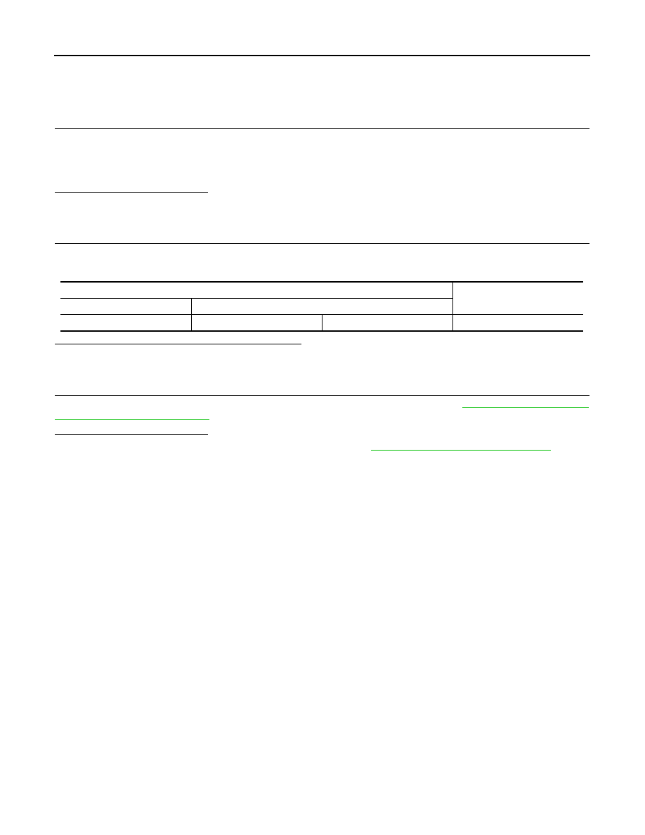
Combination meter harness connector

Resistance (

Ω)

Connector No.

Terminal No.

M24

21

22

Approx. 54 – 66

LAN

HV ECU BRANCH LINE CIRCUIT

LAN-99

< COMPONENT DIAGNOSIS >

[CAN SYSTEM (TYPE 14)]

C

D

E

F

G

H

I

J

K

L

B

A

O

P

N

HV ECU BRANCH LINE CIRCUIT

Diagnosis Procedure

INFOID:0000000004219095

1.

CHECK DTC

Check whether or not the DTC related to HEV SYSTEM CAN indicated on All DTC Reading by CONSULT-III.

NOTE:

For DTCs related to HEV SYSTEM CAN, refer to 

LAN-59, "DTC Related to HEV SYSTEM CAN List"

.

Is the DTC related to HEV SYSTEM CAN displayed?

YES

>> Inspect HEV SYSTEM CAN. Refer to 

LAN-53, "Trouble Diagnosis Flow Chart"

.

NO

>> GO TO 2.

2.

CHECK CONNECTOR

1. Turn the ignition switch OFF.

2. Disconnect the battery cable from the negative terminal.

3. Check the terminals and connectors of the hybrid vehicle control ECU for damage, bend and loose con-

nection (unit side and connector side).

Is the inspection result normal?

YES

>> GO TO 3.

NO

>> Repair the terminal and connector.

3.

CHECK HARNESS FOR OPEN CIRCUIT

1. Disconnect the connector of hybrid vehicle control ECU.

2. Check the resistance between the hybrid vehicle control ECU harness connector terminals.

Is the measurement value within the specification?

YES

>> GO TO 4.

NO

>> Repair the hybrid vehicle control ECU branch line.

4.

CHECK POWER SUPPLY AND GROUND CIRCUIT

Check the power supply and the ground circuit of the hybrid vehicle control ECU. 

HBC-600, "Wiring Diagram"

.

Is the inspection result normal?

YES (Present error)>>Replace the hybrid vehicle control ECU. Refer to 

HBC-644, "Exploded View"

.

YES (Past error)>>Error was detected in the hybrid vehicle control ECU branch line.

NO

>> Repair the power supply and the ground circuit.

Hybrid vehicle control ECU harness connector

Resistance (

Ω)

Connector No.

Terminal No.

E66

173

172

Approx. 54 – 66

LAN-100

< COMPONENT DIAGNOSIS >

[CAN SYSTEM (TYPE 14)]

IPDM-E BRANCH LINE CIRCUIT

IPDM-E BRANCH LINE CIRCUIT

Diagnosis Procedure

INFOID:0000000004219096

1.

CHECK CONNECTOR

1. Turn the ignition switch OFF.

2. Disconnect the battery cable from the negative terminal.

3. Check the terminals and connectors of the IPDM E/R for damage, bend and loose connection (unit side

and connector side).

Is the inspection result normal?

YES

>> GO TO 2.

NO

>> Repair the terminal and connector.

2.

CHECK HARNESS FOR OPEN CIRCUIT

1. Disconnect the connector of IPDM E/R.

2. Check the resistance between the IPDM E/R harness connector terminals.

Is the measurement value within the specification?

YES

>> GO TO 3.

NO

>> Repair the IPDM E/R branch line.

3.

CHECK POWER SUPPLY AND GROUND CIRCUIT

Check the power supply and the ground circuit of the IPDM E/R. Refer to 

PCS-22, "Diagnosis Procedure"

.

Is the inspection result normal?

YES (Present error)>>Replace the IPDM E/R. Refer to 

PCS-39, "Removal and Installation"

.

YES (Past error)>>Error was detected in the IPDM E/R branch line.

NO

>> Repair the power supply and the ground circuit.

IPDM E/R harness connector

Resistance (

Ω)

Connector No.

Terminal No.

E17

40

39

Approx. 108 – 132

LAN

CAN COMMUNICATION CIRCUIT

LAN-101

< COMPONENT DIAGNOSIS >

[CAN SYSTEM (TYPE 14)]

C

D

E

F

G

H

I

J

K

L

B

A

O

P

N

CAN COMMUNICATION CIRCUIT

Diagnosis Procedure

INFOID:0000000004219097

1.

CONNECTOR INSPECTION

1. Turn the ignition switch OFF.

2. Disconnect the battery cable from the negative terminal.

3. Disconnect all the unit connectors on CAN communication system.

4. Check terminals and connectors for damage, bend and loose connection.
Is the inspection result normal?

YES

>> GO TO 2.

NO

>> Repair the terminal and connector.

2.

CHECK HARNESS CONTINUITY (SHORT CIRCUIT)

Check the continuity between the data link connector terminals.

Is the inspection result normal?

YES

>> GO TO 3.

NO

>> Check the harness and repair the root cause.

3.

CHECK HARNESS CONTINUITY (SHORT CIRCUIT)

Check the continuity between the data link connector and the ground.

Is the inspection result normal?

YES

>> GO TO 4.

NO

>> Check the harness and repair the root cause.

4.

CHECK ECM AND IPDM E/R TERMINATION CIRCUIT

1. Remove the ECM and the IPDM E/R.

2. Check the resistance between the ECM terminals.

3. Check the resistance between the IPDM E/R terminals.

Is the measurement value within the specification?

YES

>> GO TO 5.

NO

>> Replace the ECM and/or the IPDM E/R.

5.

CHECK SYMPTOM

Connect all the connectors. Check if the symptoms described in the “Symptom (Results from interview with

customer)” are reproduced. 

Data link connector

Continuity

Connector No.

Terminal No.

M22

6

14

Not existed

Data link connector

Ground

Continuity

Connector No.

Terminal No.

M22

6

Not existed

14

Not existed

ECM

Resistance (

Ω)

Terminal No.

98

97

Approx. 108 – 132

IPDM E/R

Resistance (

Ω)

Terminal No.

40

39

Approx. 108 – 132

LKIA0037E


Content   ..  784  785  786  787   ..