Nissan Altima HL32 Hybrid. Manual - part 770


  Index      Nissan     Nissan Altima HL32 Hybrid (2009 year) - Service and Repair Manual


Search            


Content   ..  768  769  770  771   ..


Nissan Altima HL32 Hybrid. Manual - part 770


LAN-34

< COMPONENT DIAGNOSIS >

[CAN]

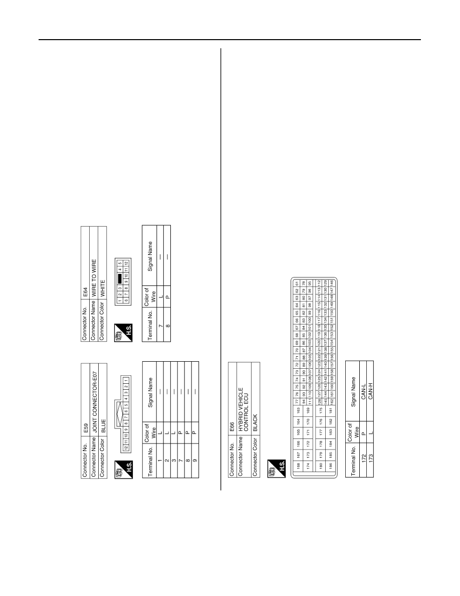
CAN COMMUNICATION SYSTEM

AWMIA0187GB

LAN

MALFUNCTION AREA CHART

LAN-35

< COMPONENT DIAGNOSIS >

[CAN]

C

D

E

F

G

H

I

J

K

L

B

A

O

P

N

MALFUNCTION AREA CHART

Main Line

INFOID:0000000004219036

Branch Line

INFOID:0000000004219037

Short Circuit

INFOID:0000000004219038

Malfunction Area

Reference

Main line between data link connector and hybrid vehicle control ECU

LAN-36, "Diagnosis Procedure"

Malfunction Area

Reference

ECM branch line circuit 

LAN-37, "Diagnosis Procedure"

Air bag diagnosis sensor unit branch line circuit 

LAN-38, "Diagnosis Procedure"

AV control unit branch line circuit 

LAN-39, "Diagnosis Procedure"

BCM branch line circuit 

LAN-40, "Diagnosis Procedure"

Data link connector branch line circuit 

LAN-41, "Diagnosis Procedure"

Controller (auto amp.) branch line circuit 

LAN-42, "Diagnosis Procedure"

Combination meter branch line circuit 

LAN-43, "Diagnosis Procedure"

Hybrid vehicle control ECU branch line circuit 

LAN-44, "Diagnosis Procedure"

IPDM E/R branch line circuit 

LAN-45, "Diagnosis Procedure"

Malfunction Area

Reference

CAN communication circuit

LAN-46, "Diagnosis Procedure"

LAN-36

< COMPONENT DIAGNOSIS >

[CAN]

MAIN LINE BETWEEN DLC AND HV ECU CIRCUIT

MAIN LINE BETWEEN DLC AND HV ECU CIRCUIT

Diagnosis Procedure

INFOID:0000000004219039

INSPECTION PROCEDURE

1.

CHECK CONNECTOR

1. Turn the ignition switch OFF.

2. Disconnect the battery cable from the negative terminal.

3. Check the following terminals and connectors for damage, bend and loose connection (connector side

and harness side).

-

Harness connector M89

-

Harness connector E64

Is the inspection result normal?

YES

>> GO TO 2.

NO

>> Repair the terminal and connector.

2.

CHECK HARNESS CONTINUITY (OPEN CIRCUIT)

1. Disconnect the harness connectors M89 and E64.

2. Check the continuity between the data link connector and the harness connector.

Is the inspection result normal?

YES

>> GO TO 3.

NO

>> Repair the main line between the data link connector and the harness connector M89.

3.

CHECK HARNESS CONTINUITY (OPEN CIRCUIT)

1. Disconnect the connector of hybrid vehicle control ECU.

2. Check the continuity between the harness connector and the hybrid vehicle control ECU harness connec-

tor.

Is the inspection result normal?

YES (Present error)>>Check CAN system type decision again.

YES (Past error)>>Error was detected in the main line between the data link connector and the hybrid vehi-

cle control ECU. 

NO

>> Repair the main line between the harness connector E64 and the hybrid vehicle control ECU.

Data link connector

Harness connector

Continuity

Connector No.

Terminal No.

Connector No.

Terminal No.

M22

6

M89

7

Existed

14

8

Existed

Harness connector

Hybrid vehicle control ECU harness connector

Continuity

Connector No.

Terminal No.

Connector No.

Terminal No.

E64

7

E66

173

Existed

8

172

Existed

LAN

ECM BRANCH LINE CIRCUIT

LAN-37

< COMPONENT DIAGNOSIS >

[CAN]

C

D

E

F

G

H

I

J

K

L

B

A

O

P

N

ECM BRANCH LINE CIRCUIT

Diagnosis Procedure

INFOID:0000000004219040

1.

CHECK CONNECTOR

1. Turn the ignition switch OFF.

2. Disconnect the battery cable from the negative terminal.

3. Check the following terminals and connectors for damage, bend and loose connection (unit side and con-

nector side).

-

ECM

-

Harness connector E47

-

Harness connector E48

-

Junction block

-

Harness connector E30

-

Harness connector M1

Is the inspection result normal?

YES

>> GO TO 2.

NO

>> Repair the terminal and connector.

2.

CHECK HARNESS FOR OPEN CIRCUIT

1. Disconnect the connector of ECM.

2. Check the resistance between the ECM harness connector terminals.

Is the measurement value within the specification?

YES

>> GO TO 3.

NO

>> Repair the ECM branch line.

3.

CHECK POWER SUPPLY AND GROUND CIRCUIT

Check the power supply and the ground circuit of the ECM. Refer to 

EC-114, "Diagnosis Procedure"

.

Is the inspection result normal?

YES (Present error)>>Replace the ECM. Refer to 

EC-14, "ADDITIONAL SERVICE WHEN REPLACING

CONTROL UNIT : Special Repair Requirement"

.

YES (Past error)>>Error was detected in the ECM branch line.

NO

>> Repair the power supply and the ground circuit.

ECM harness connector

Resistance (

Ω)

Connector No.

Terminal No.

E10

98

97

Approx. 108 – 132


Content   ..  768  769  770  771   ..