Nissan Altima HL32 Hybrid. Manual - part 707


  Index      Nissan     Nissan Altima HL32 Hybrid (2009 year) - Service and Repair Manual


Search            


Content   ..  705  706  707  708   ..


Nissan Altima HL32 Hybrid. Manual - part 707


U0110-159, U0110-160, U0110-656, U0110-657

HBC-577

< COMPONENT DIAGNOSIS >

D

E

F

G

H

I

J

K

L

M

A

B

HBC

N

O

P

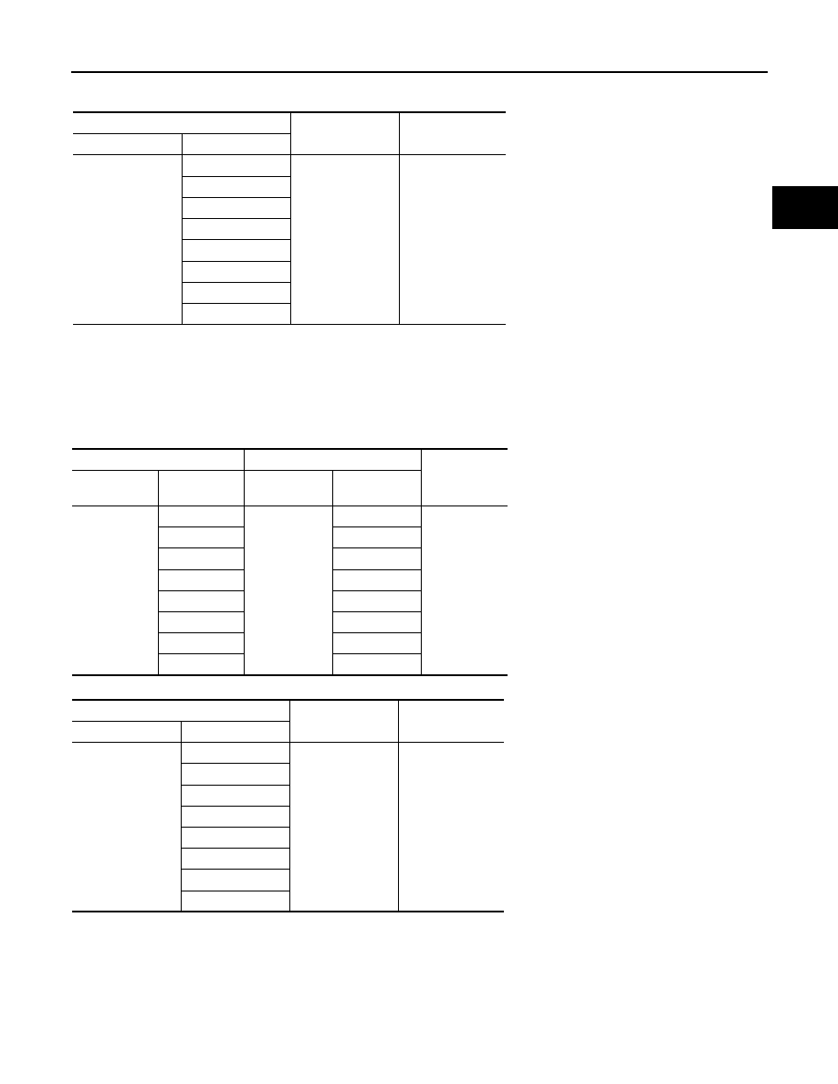
4. Measure the voltage according to the value(s) in the table below.

NOTE:

Turn ignition switch ON with the low voltage connector of the inverter with converter assembly or hybrid

vehicle control ECU connector disconnected causes other DTCs to be stored. Clear the DTCs after per-

forming this inspection.

5. Turn ignition switch OFF.

6. Measure the resistance according to the value(s) in the table below.

Check for open

Check for short

Hybrid vehicle control ECU

Ground

Voltage

Harness connector

Terminal

E66

184 (CLK+)

Ground

Below 1V

178 (CLK-)

185 (REQ+)

179 (REQ-)

182 (HTM+)

176 (HTM-)

183 (MTH+)

177 (MTH -)

Hybrid vehicle control ECU

Inverter with converter assembly

Resistance

Harness

connector

Terminal

Harness

connector

Terminal

E66

184 (CLK+)

E69

15 (CLK+)

Below 1

178 (CLK-)

24 (CLK-)

185 (REQ+)

18 (REQ+)

179 (REQ-)

27 (REQ-)

182 (HTM+)

17 (HTM+)

176 (HTM-)

26 (HTM-)

183 (MTH+)

19 (MTH+)

177 (MTH -)

28 (MTH -)

Hybrid vehicle control ECU

Ground

Resistance

Harness connector

Terminal

E66

184 (CLK+)

Ground

10 k

Ω or higher

178 (CLK-)

185 (REQ+)

179 (REQ-)

182 (HTM+)

176 (HTM-)

183 (MTH+)

177 (MTH -)

HBC-578

< COMPONENT DIAGNOSIS >

U0110-159, U0110-160, U0110-656, U0110-657

Check for short

OK or NG

OK

>> GO TO 8.

NG

>> Repair or replace harness or connector.

8.

CHECK HYBRID VEHICLE CONTROL ECU

1. Turn ignition switch OFF.

2. Connect the hybrid vehicle control ECU connector.

3. Measure the resistance according to the value(s) in the table below.

OK or NG

OK

>> GO TO 9.

NG

>> Replace hybrid vehicle control ECU. (See 

HBC-644, "Removal and Installation"

)

9.

CHECK INVERTER WITH CONVERTER ASSEMBLY

1. Turn ignition switch OFF.

2. Connect the inverter with converter assembly connector.

3. Disconnect the E66 hybrid vehicle control ECU connector.

4. Measure the resistance according to the value(s) in the table

below.

OK or NG

OK

>> GO TO 10.

NG

>> Replace inverter with converter assembly. (See 

HBC-638, "Removal and Installation"

).

10.

CHECK NOISE SOURCE

NOTE:

Using non-genuine parts may cause electrical noise to be introduced.

Inverter with converter assembly

Ground

Resistance

Harness connector

Terminal

E69

15 (CLK+)

Ground

10 k

Ω or higher

24 (CLK-)

18 (REQ+)

27 (REQ-)

17 (HTM+)

26 (HTM-)

19 (MTH+)

28 (MTH -)

Inverter with converter assembly Inverter with converter assembly

Resistance

Harness

connector

Terminal

Harness

connector

Terminal

E69

15 (CLK+)

E69

24 (CLK-)

109 to 139 

18 (REQ+)

27 (REQ-)

17 (HTM+)

26 (HTM-)

19 (MTH+)

28 (MTH -)

Hybrid vehicle control ECU (A)

Hybrid vehicle control ECU (A)

Resistance

Harness

connector

Terminal

Harness

connector

Terminal

E66

184 (CLK+)

E66

178 (CLK-)

109 to 139

185 (REQ+)

179 (REQ-)

182 (HTM+)

176 (HTM-)

183 (MTH+)

177(MTH-)

JMCIA0243GB

U0110-159, U0110-160, U0110-656, U0110-657

HBC-579

< COMPONENT DIAGNOSIS >

D

E

F

G

H

I

J

K

L

M

A

B

HBC

N

O

P

Electrical noise is introduced

YES

>> Repair or replace noise source.

NO

>> GO TO 11.

11.

REPLACE HYBRID VEHICLE CONTROL ECU

See 

HBC-644, "Removal and Installation"

.

>> GO TO 12.

12.

CLEAR DTC

1. Turn ignition switch ON.

2. Check DTC.
DTC P0A09-591 is output

>> GO TO 13.

13.

RECONFIRM DTC OUTPUT (HYBRID SYSTEM)

1. Turn ignition switch ON.

2. Check DTC.
DTC U0110-159, 160, 656 or 657 is output

YES

>> Replace inverter with converter assembly. (See 

HBC-638, "Removal and Installation"

).

NO

>> Completed.

HBC-580

< COMPONENT DIAGNOSIS >

U0115-901

U0115-901

Description

INFOID:0000000004212175

The hybrid vehicle control ECU transmits and receives signals to and from the ECM through CAN communica-

tion line. When the ECM sends the same P-RUN signal to the hybrid vehicle control ECU for 2 seconds, the

hybrid vehicle control ECU will set a DTC U0115-901.

DTC Logic

INFOID:0000000004212176

DTC DETECTION LOGIC

DTC CONFIRMATION PROCEDURE

1.

PRECONDITIONING

If DTC confirmation procedure has been previously conducted, always turn ignition switch OFF and wait at

least 10 seconds before conducting the next test.

If DTC U0115-901 is displayed with DTC P0A1D-924 or P0A1D-925, first perform the diagnosis procedure for

P0A1D-924, P0A1D-925.

>> GO TO 2.

2.

PERFORM DTC CONFIRMATION PROCEDURE

1. Turn ignition switch ON and wait at least 3 seconds.

2. Check DTC.
Is DTC detected?

YES

>> Go to 

HBC-580, "Diagnosis Procedure"

.

NO

>> INSPECTION END

Diagnosis Procedure

INFOID:0000000004212177

1.

PRECONDITIONING

• Before inspecting the high-voltage system or disconnecting the low voltage connector of the inverter with

converter assembly, take safety precautions such as wearing insulated gloves and removing the service

plug grip to prevent electrical shocks. After removing the service plug grip, put it in your pocket to prevent

other technicians from accidentally reconnecting it while you are working on the high-voltage system.

• After disconnecting the service plug grip, wait for at least 10 minutes before touching any of the high-voltage

connectors or terminals.

• Waiting for at least 10 minutes is required to discharge the high-voltage capacitor inside the inverter with

converter assembly.

>> GO TO 2.

2.

CHECK HARNESS CONTINUITY BETWEEN HYBRID VEHICLE CONTROL ECU AND ECM

Refer to 

LAN-4, "Description"

.

OK or NG

OK

>> GO TO 3.

NG

>> Repair or replace harness or connectors.

3.

CHECK DTC OUTPUT (ENGINE)

1. Turn ignition switch ON.

2. Check DTC for engine control system.
Is DTC detected?

DTC No.

INF code

Trouble diagnosis name

DTC detecting condition

Possible cause

U0115

901

Lost communication with ECM/
PCM “B”

The hybrid vehicle control ECU 
receives malfunction signal of P-
RUN signal from ECM.

• Hybrid vehicle control ECU


Content   ..  705  706  707  708   ..