Nissan Altima HL32 Hybrid. Manual - part 686


  Index      Nissan     Nissan Altima HL32 Hybrid (2009 year) - Service and Repair Manual


Search            


Content   ..  684  685  686  687   ..


Nissan Altima HL32 Hybrid. Manual - part 686


P1805-903, P1805-923

HBC-493

< COMPONENT DIAGNOSIS >

D

E

F

G

H

I

J

K

L

M

A

B

HBC

N

O

P

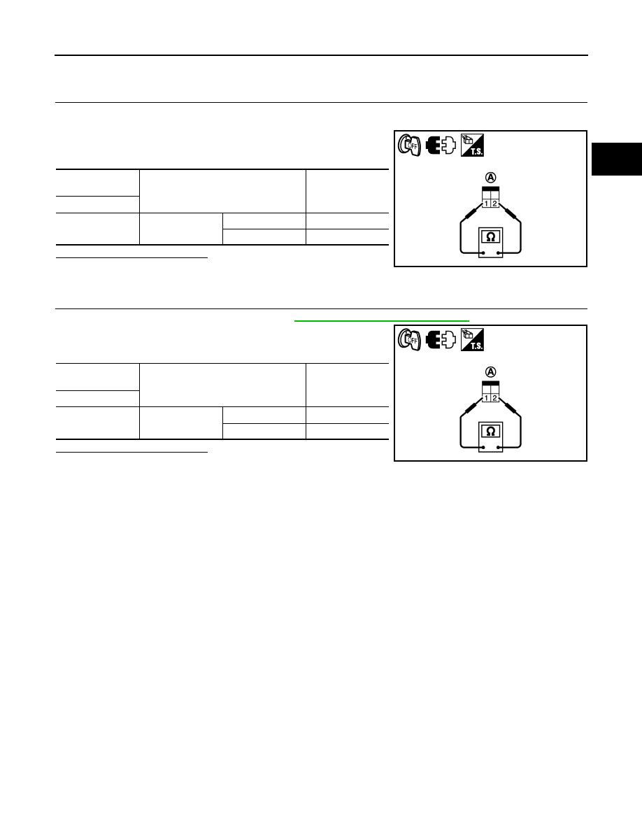
Component Inspection (Stop Lamp Switch)

INFOID:0000000004212099

1.

CHECK STOP LAMP SWITCH-I

1. Turn ignition switch OFF.

2. Disconnect stop lamp switch harness connector.

3. Check the continuity between stop lamp switch terminals under

the following conditions.

Is the inspection result normal?

YES

>> INSPECTION END

NO

>> GO TO 2.

2.

CHECK STOP LAMP SWITCH-II

1. Adjust stop lamp switch installation. Refer to 

BR-12, "Inspection and Adjustment"

.

2. Check the continuity between stop lamp switch terminals under

the following conditions.

Is the inspection result normal?

YES

>> INSPECTION END

NO

>> Replace stop lamp switch.

Stop lamp switch 

(A)

Condition

Continuity

Terminals

1 and 2

Brake pedal

Fully released

Not existed

Slightly depressed

Existed

JMCIA0235ZZ

Stop lamp switch 

(A)

Condition

Continuity

Terminals

1 and 2

Brake pedal

Fully released

Not existed

Slightly depressed

Existed

JMCIA0235ZZ

HBC-494

< COMPONENT DIAGNOSIS >

P2120-152, P2121-106, P2122-104, P2123-105, 2125-153

P2120-152, P2121-106, P2122-104, P2123-105, 2125-153

Description

INFOID:0000000004212100

The accelerator pedal position sensor is installed on the upper end

of the accelerator pedal assembly. The sensor detects the accelera-

tor position and sends a signal to the hybrid vehicle control ECU.

Accelerator pedal position sensor has two sensors. These sensors

are a kind of potentiometers which transform the accelerator pedal

position into output voltage, and emit the voltage signal to the hybrid

vehicle control ECU. The sensor 1 signal is used to detect the accel-

erator pedal position and the sensor 2 signal is used as a confirma-

tion to allow the detection of malfunction in the sensor itself. In

addition, these sensors detect how much the accelerator pedal is

depressed and feed the voltage signals to the hybrid vehicle control

ECU. The hybrid vehicle control ECU judges the current opening

angle of the accelerator pedal from these signals, and sends the engine speed request signal and engine

power request signal to the ECM. The ECM controls the throttle control motor based on these signals. Further-

more, the hybrid vehicle control ECU uses these signals for operating motor torque.

Idle position of the accelerator pedal is determined by the hybrid vehicle control ECU receiving the signal from

the accelerator pedal position sensor. The hybrid vehicle control ECU uses this signal for various engine oper-

ation.

DTC Logic

INFOID:0000000004212101

DTC DETECTION LOGIC

Diagnosis Procedure

INFOID:0000000004212102

1.

PRECONDITIONING

• Before inspecting the high-voltage system or disconnecting the low voltage connector of the inverter with

converter assembly, take safety precautions such as wearing insulated gloves and removing the service

JMCIA0170GB

DTC No.

INF code

Trouble diagnosis name

DTC detecting condition

Possible cause

P2120

152

Throttle/pedal position sensor/
switch “D” circuit

Main sensor circuit malfunction 
or level is not stable

• Wire harness or connector
• Accelerator pedal assembly
• Hybrid vehicle control ECU

P2121

106

Throttle/pedal position sensor/
switch “D” circuit range/perfor-
mance

Internal error of the main sensor

P2122

104

Throttle/pedal position sensor/
switch “D” circuit low input

Open or short to GND in the main 
sensor circuit

P2123

105

Throttle/pedal position sensor/
switch “D” circuit high input

Short to +B in the main sensor 
circuit

P2125

153

Throttle/pedal position sensor/
switch “E” circuit

Sub sensor circuit wiring mal-
function or level is not stable

P2126

109

Throttle/pedal position sensor/
switch “E” circuit range/perfor-
mance

Internal error of the sub sensor

P2127

107

Throttle/pedal position sensor/
switch “E” circuit low input

Open or short to GND in the sub 
sensor circuit

P2128

108

Throttle/pedal position sensor/
switch “E” circuit high input

Short to +B in the sub sensor cir-
cuit

P2138

110

Throttle/pedal position sensor/
switch “D”/“E” voltage correla-
tion

Difference between the main 
sensor value and sub sensor val-
ue is large or small.

P2138

154

Throttle/pedal position sensor/
switch “D”/“E” voltage correla-
tion

Main or sub sensor circuit wiring 
malfunction

P2120-152, P2121-106, P2122-104, P2123-105, 2125-153

HBC-495

< COMPONENT DIAGNOSIS >

D

E

F

G

H

I

J

K

L

M

A

B

HBC

N

O

P

plug grip to prevent electrical shocks. After removing the service plug grip, put it in your pocket to prevent

other technicians from accidentally reconnecting it while you are working on the high-voltage system.

• After disconnecting the service plug grip, wait for at least 10 minutes before touching any of the high-voltage

connectors or terminals.

• Waiting for at least 10 minutes is required to discharge the high-voltage capacitor inside the inverter with

converter assembly.

>> GO TO 2.

2.

READ VALUE OF CONSULT-III

1. Turn ignition switch ON.

2. Select “ACCEL SENSOR 1” and “ACCEL SENSOR 2” in “DATA MONITOR” mode with CONSULT-III.

3. Read the indication.

NOTE:

5V is described as 100% on the tester.

OK or NG

OK

>> Check for intermittent incident.

NG

>> GO TO 3.

3.

CHECK CONNECTOR CONNECTION CONDITION (HYBRID VEHICLE CONTROL ECU CONNECTOR)

Refer to 

HBC-109, "Diagnosis Procedure"

.

OK or NG

OK

>> GO TO 4.

NG

>> Connect securely.

4.

CHECK CONNECTOR CONNECTION CONDITION (ACCELERATOR LINK ROD ASSEMBLY CONNEC-

TOR)

Check the connections of the accelerator link rod assembly connector.
OK or NG

OK

>> GO TO 5.

NG

>> Connect securely.

5.

CHECK HYBRID VEHICLE CONTROL ECU

1. Disconnect the E40 accelerator pedal position sensor connector.

2. Turn ignition switch ON.

3. Measure the voltage according to the value(s) in the table below.

NOTE:

Turn ignition switch ON with the accelerator pedal position sen-

sor connector disconnected causes other DTCs to be stored.

Clear the DTCs after performing this inspection.

Pedal Condition

ACCEL SENSOR 1

ACCEL SENSOR 2

Not depressed

(8 to 28%) 0.4 to 1.4 V

(24 to 44%) 1.2 to 2.2 V

Fully depressed

(52 to 90%) 2.6 to 4.5 V

(68 to 100%) 3.4 to 5.3 V

Not depressed
→ Fully depressed
→ Not depressed
(Accelerator pedal should 
be operated slowly)

Value changes

progressively

Value changes

progressively

Accelerator pedal position sen-

sor (A)

Accelerator pedal position sen-

sor (A)

Voltage

Harness

connector

Terminal

Harness

connector

Terminal

E40

4 (VC1)

E40

5 (GND1)

4.5 to 5.5V

1 (VC2)

2 (GND2)

JMCIA0236GB

HBC-496

< COMPONENT DIAGNOSIS >

P2120-152, P2121-106, P2122-104, P2123-105, 2125-153

OK or NG

OK

>> GO TO 6.

NG

>> GO TO 8.

6.

CHECK HYBRID VEHICLE CONTROL ECU

1. Turn ignition switch OFF.

2. Measure the resistance according to the value(s) in the table

below.

OK or NG

OK

>> Replace accelerator pedal position sensor. (See 

ACC-3, "Removal and Installation"

).

NG

>> GO TO 7.

7.

CHECK HARNESS AND CONNECTOR (HYBRID VEHICLE CONTROL ECU - ACCELERATOR PEDAL

POSITION SENSOR)
1. Turn ignition switch OFF.

2. Disconnect the E66 hybrid vehicle control ECU connector.

3. Turn ignition switch ON.

4. Measure the voltage according to the value(s) in the table below.

NOTE:

Turn ignition switch ON with the accelerator pedal position sensor and hybrid vehicle control ECU connec-

tors disconnected causes other DTCs to be stored. Clear the DTCs after performing this inspection.

5. Turn ignition switch OFF.

6. Measure the resistance according to the value(s) in the table below.

Accelerator pedal position sen-

sor (A)

Accelerator pedal position sen-

sor (A)

Resistance

Harness

connector

Terminal

Harness

connector

Terminal

E40

6 (VPA1)

E40

5 (GND1)

37 to 41 k

3 (VPA2)

2 (GND2)

JMCIA0237GB

Hybrid vehicle control ECU

Ground

Voltage

Harness

connector

Terminal

E66

147 (VPA)

Ground

Below 1V

130 (EP1)

146 (VPA2)

129 (EP2)

Hybrid vehicle control ECU

Accelerator pedal position sensor

Resistance

Harness connector

Terminal

Harness connector

Terminal

E66

147 (VPA)

E40

6 (VPA1)

Below 1

113 (VCP1)

4 (VC1)

130 (EP1)

5 (GND1)

146 (VPA2)

3 (VPA2)

112 (VCP2)

1 (VC2)

129 (EP2)

2 (GND2)


Content   ..  684  685  686  687   ..