Nissan Altima HL32 Hybrid. Manual - part 651
P0A90-509
HBC-353
< COMPONENT DIAGNOSIS >
D
E
F
G
H
I
J
K
L
M
A
B
HBC
N
O
P
P0A90-509
Description
INFOID:0000000004211990
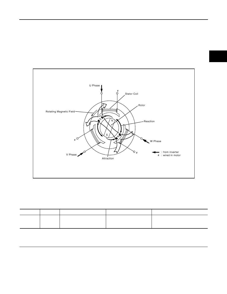
When three-phase alternating current flows through the three-phase windings of the stator coil, a rotating
magnetic field is generated in MG2. The system controls the rotation of the magnetic field in accordance with
the rotating position and speed of the rotor. As a result, the permanent magnets provided in the rotor are
pulled in the direction of rotation, generating torque. The generated torque is almost proportional to the
amount of current. The system controls MG2 speed by regulating the frequency of the alternating current. Fur-
thermore, the system properly controls the rotating magnetic field and the angle of the rotor magnets in order
to generate high torque in an efficient manner, even at high speeds.
DTC Logic
INFOID:0000000004211991
DTC DETECTION LOGIC
The MG ECU monitors the MG2 system. If the MG ECU detects a malfunction of the MG2 system, the hybrid
vehicle control ECU will illuminate the MIL and set a DTC.
Diagnosis Procedure
INFOID:0000000004211992
1.
PRECONDITIONING
• Before inspecting the high-voltage system or disconnecting the low voltage connector of the inverter with
converter assembly, take safety precautions such as wearing insulated gloves and removing the service
plug grip to prevent electrical shocks. After removing the service plug grip, put it in your pocket to prevent
other technicians from accidentally reconnecting it while you are working on the high-voltage system.
• After disconnecting the service plug grip, wait for at least 10 minutes before touching any of the high-voltage
connectors or terminals.
• Waiting for at least 10 minutes is required to discharge the high-voltage capacitor inside the inverter with
converter assembly.
JMCIA0101GB
DTC No.
INF code
Trouble diagnosis name
DTC detecting condition
Possible cause
P0A90
509
Drive Motor “A” Performance
Motor system malfunction
• Wire harness or connector
• Hybrid transaxle
• Inverter with converter assembly