Nissan Altima HL32 Hybrid. Manual - part 619


  Index      Nissan     Nissan Altima HL32 Hybrid (2009 year) - Service and Repair Manual


Search            


Content   ..  617  618  619  620   ..


Nissan Altima HL32 Hybrid. Manual - part 619


P0A78-113

HBC-225

< COMPONENT DIAGNOSIS >

D

E

F

G

H

I

J

K

L

M

A

B

HBC

N

O

P

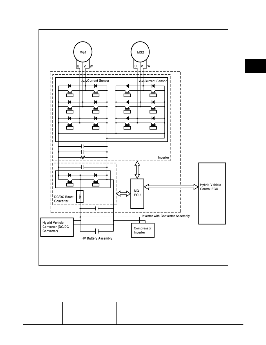
The MG ECU monitors the inverter voltage and detects malfunctions.

DTC Logic

INFOID:0000000004211907

DTC DETECTION LOGIC

If MG ECU detects overheat or circuit malfunction of the traction motor inverter, the inverter assembly trans-

mits this information via the traction motor inverter fail signal line.

JMCIA0099GB

DTC No.

INF Code

Trouble diagnosis name

DTC detecting condition

Possible cause

P0A78

113

Drive Motor “A” Inverter Perfor-
mance

Motor inverter fail signal detection 
(overcurrent due to system mal-
function)

• Wire harness or connector
• Hybrid transaxle
• Inverter with converter assembly

HBC-226

< COMPONENT DIAGNOSIS >

P0A78-113

Diagnosis Procedure

INFOID:0000000004211908

1.

PRECONDITIONING

• Before inspecting the high-voltage system or disconnecting the low voltage connector of the inverter with

converter assembly, take safety precautions such as wearing insulated gloves and removing the service

plug grip to prevent electrical shocks. After removing the service plug grip, put it in your pocket to prevent

other technicians from accidentally reconnecting it while you are working on the high-voltage system.

• After disconnecting the service plug grip, wait for at least 10 minutes before touching any of the high-voltage

connectors or terminals.

• Waiting for at least 10 minutes is required to discharge the high-voltage capacitor inside the inverter with

converter assembly.

>> GO TO 2.

2.

CHECK DTC OUTPUT (HYBRID SYSTEM)

1. Turn ignition switch ON.

2. Check DTC.

NOTE:

P0A78-113 may be set due to a malfunction which also causes DTCs in the table above to be set. In this case,

first troubleshoot the output DTCs in the table above. Then, perform a test to attempt to reproduce the prob-

lems, and check that no DTCs are output.
Is DTC detected?

YES

>> Go to Diagnosis Procedure relevant to output DTC.

NO

>> GO TO 3.

3.

CHECK CONNECTOR CONNECTION CONDITION (INVERTER WITH CONVERTER ASSEMBLY CON-

NECTOR)
See 

HBC-109, "Diagnosis Procedure"

.

OK or NG

OK

>> GO TO 4.

DTC No.

Relevant Diagnosis

P0A1D (Except INF code 390)

Hybrid Powertrain Control Module

P0A1A (all INF codes)

Generator Control Module

P0A1B (all INF codes)

Drive Motor “A” Control Module

P0A72 (all INF codes)

Generator Phase V Current

P0A75 (all INF codes)

Generator Phase W Current

P0A60 (all INF codes)

Drive Motor “A” Phase V Current

P0A63 (all INF codes)

Drive Motor “A” Phase W Current

P0A4B-253

Generator Position Sensor Circuit

P0A4D-255

Generator Position Sensor Circuit Low

P0A4C-513

Generator Position Sensor Circuit Range/Performance

P0A3F-243

Drive Motor “A” Position Sensor Circuit

P0A41-245

Drive Motor “A” Position Sensor Circuit Low

P0A40-500

Drive Motor “A” Position Sensor Circuit Range / Performance

P0A78-266, 267, 523, 586, 505, 287, 506, 503, 279, 
504, 306, 806, 807, 808

Drive Motor “A” Inverter Performance

P0A94-585, 587, 589, 590, 554, 555, 556, 547, 548, 
549, 442

DC/DC Converter Performance

P0A7A-517, 325, 518, 344, 809, 810, 811

Generator Inverter Performance

P0A92-521

Hybrid Generator Performance

P0A90-509

Drive Motor “A” Performance

P0A78-113

HBC-227

< COMPONENT DIAGNOSIS >

D

E

F

G

H

I

J

K

L

M

A

B

HBC

N

O

P

NG

>> CONNECT SECURELY

4.

CHECK HARNESS AND CONNECTOR (INVERTER WITH CONVERTER ASSEMBLY - GENERATOR RE-

SOLVER)

See 

HBC-164, "Diagnosis Procedure"

.

OK or NG

OK

>> GO TO 5.

NG

>> Repair or replace harness or connector.

5.

CHECK GENERATOR RESOLVER

See 

HBC-164, "Diagnosis Procedure"

OK or NG

OK

>> GO TO 6.

NG

>> GO TO 12.

6.

CHECK HARNESS AND CONNECTOR (INVERTER WITH CONVERTER ASSEMBLY - MOTOR RESOLV-

ER)

See 

HBC-171, "Diagnosis Procedure"

OK or NG

OK

>> GO TO 7.

NG

>> Repair or replace harness or connector.

7.

CHECK MOTOR RESOLVER

See 

HBC-171, "Diagnosis Procedure"

OK or NG

OK

>> GO TO 8.

NG

>> GO TO 14.

8.

CHECK INVERTER WITH CONVERTER ASSEMBLY (GENERATOR CABLE CONNECTION CONDITION)

See 

HBC-177, "Diagnosis Procedure"

OK or NG

OK

>> GO TO 9.

NG

>> Tighten to specified torque.

9.

CHECK INVERTER WITH CONVERTER ASSEMBLY (MOTOR CABLE CONNECTION CONDITION)

See 

HBC-177, "Diagnosis Procedure"

OK or NG

OK

>> GO TO 10.

NG

>> Tighten to specified torque.

10.

INSPECT HYBRID TRANSAXLE (MG1)

See 

HBC-177, "Diagnosis Procedure"

OK or NG

OK

>> GO TO 11.

NG

>> Replace hybrid transaxle (See 

TM-36, "Removal and Installation"

.)

11.

INSPECT HYBRID TRANSAXLE (MG2)

See 

HBC-177, "Diagnosis Procedure"

OK or NG

OK

>> Replace inverter with converter assembly (See 

HBC-638, "Removal and Installation"

.)

NG

>> Replace hybrid transaxle (See 

TM-36, "Removal and Installation"

.)

12.

CHECK CONNECTOR CONNECTION CONDITION (GENERATOR RESOLVER CONNECTOR)

See 

HBC-164, "Diagnosis Procedure"

OK or NG

OK

>> GO TO 13.

HBC-228

< COMPONENT DIAGNOSIS >

P0A78-113

NG

>> Connect securely.

13.

CHECK HARNESS AND CONNECTOR (INVERTER WITH CONVERTER ASSEMBLY - GENERATOR

RESOLVER)
See 

HBC-164, "Diagnosis Procedure"

OK or NG

OK

>> Replace hybrid transaxle (See 

TM-36, "Removal and Installation"

.)

NG

>> Repair or replace harness or connector.

14.

CHECK CONNECTOR CONNECTION CONDITION (MOTOR RESOLVER CONNECTOR)

See 

HBC-171, "Diagnosis Procedure"

OK or NG

OK

>> GO TO 15.

NG

>> Connect securely.

15.

CHECK HARNESS AND CONNECTOR (INVERTER WITH CONVERTER ASSEMBLY - MOTOR RE-

SOLVER)
See 

HBC-171, "Diagnosis Procedure"

OK or NG

OK

>> Replace hybrid transaxle (See 

TM-36, "Removal and Installation"

.)

NG

>> Repair or replace harness or connector.


Content   ..  617  618  619  620   ..