Nissan Altima HL32 Hybrid. Manual - part 521
 

  Index      Nissan     Nissan Altima HL32 Hybrid (2009 year) - Service and Repair Manual


Search            


Content   ..  519  520  521  522   ..


Nissan Altima HL32 Hybrid. Manual - part 521


HV ECU

HAC-105

< ECU DIAGNOSIS >

[AUTOMATIC AIR CONDITIONER]

C

D

E

F

G

H

J

K

L

M

A

B

HAC

N

O

P

56

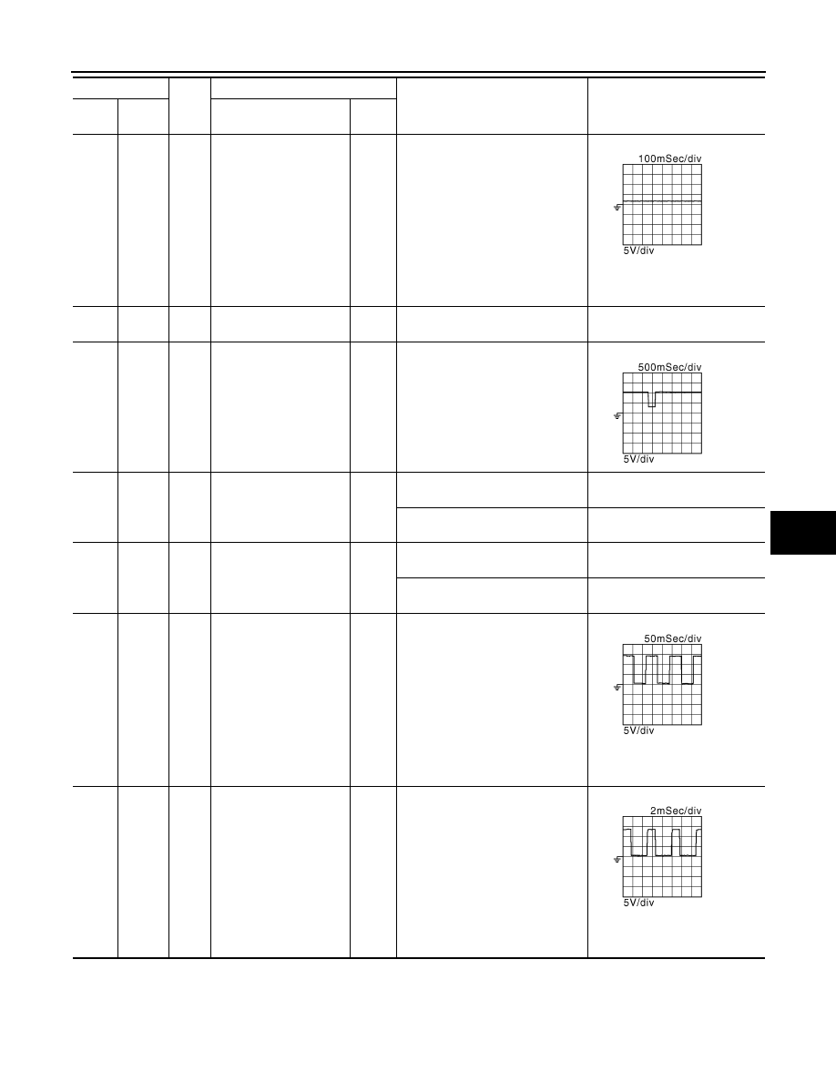
Ground

W

Compressor inverter 
communication

[Ignition switch: READY]

The wave form will vary depend-
ing on the content of the digital 
communication (digital signal).

60

Ground

P

Power supply for PNP 
switch

[Ignition switch: ON]

BATTERY VOLTAGE
(11 - 14V)

77

Ground

L/B

HV battery assembly
(SMRP operation signal)

[Ignition switch: ON to READY]

82

Ground

G/B

Back up lamp relay

Output

[Ignition switch: ON]
• Shift position: R

0 - 1.5V

[Ignition switch: ON]
• Shift position: Except above

BATTERY VOLTAGE
(11 - 14V)

94

Ground GR/R

MG ECU communication
(Interlock switch signal)

Input

[Ignition switch: ON]
• Service plug grip: Connect

0 - 1.5V

[Ignition switch: ON]
• Service plug grip: Disconnect

BATTERY VOLTAGE
(11 - 14V)

100

Ground

L

ECM
(PHASE signal)

Input

[Engine is running]
• Idle speed

NOTE:
The pulse cycle changes de-
pending on rpm at idle.

The pulse cycle becomes short-
er as the engine speed in-
creased.

101

Ground

P

ECM
(POS signal)

Input

[Engine is running]
• Idle speed

The pulse cycle becomes short-
er as the engine speed in-
creased.

Terminal No.

Wire 

color

Description

Condition

Value

(Approx.)

+

Signal name

Input/

Output

JMCIA0006GB

JMCIA0007GB

JMCIA0008GB

JMCIA0009GB

HAC-106

< ECU DIAGNOSIS >

[AUTOMATIC AIR CONDITIONER]

HV ECU

102

Ground

L/O

Brake ECU
(Vehicle speed signal)

Input

[Ignition switch: READY]
• Vehicle speed: 20 km/h (12 

MPH)

The higher the vehicle speed, 
the shorter the cycle.

103

Ground

GR

HV battery assembly
(DC/DC converter opera-
tion signal)

Input

[Ignition switch: ON]

0.1 - 0.5V

[Ignition switch: READY]

5 - 7V

104

Ground

G/R

HV battery assembly
(DC/DC converter opera-
tion signal)

Input

[Ignition switch: ON]

The cycle will vary depending on 
the specified voltage of the hy-
brid vehicle converter.

105

Ground

Y/R

HV battery blower fan 
motor

[Ignition switch: ON]
• During ACTIVE TEST

109

Ground

R

Inverter water pump

[Ignition switch: READY]

112

Ground

O

Sensor power supply
(Accelerator pedal posi-
tion sensor 2)

[Ignition switch: ON]

5V

113

Ground

O/L

Sensor power supply
(Accelerator pedal posi-
tion sensor 1)

[Ignition switch: ON]

5V

118

Ground

G/B

ASCD brake switch

Input

[Ignition switch: OFF]
• Brake pedal: Fully released

BATTERY VOLTAGE
(11 - 14V)

[Ignition switch: OFF]
• Brake pedal: Slightly depressed

0 - 1.5V

121

Ground

L/W

MG ECU communication
(MG shutdown signal)

Input

[Ignition switch: ON]
[Ignition switch: READY]

0 - 1.5V

129

Ground

W/L

Sensor ground
(Accelerator pedal posi-
tion sensor 2)

[Ignition switch: READY]

0V

Terminal No.

Wire 

color

Description

Condition

Value

(Approx.)

+

Signal name

Input/

Output

JMCIA0009GB

JMCIA0011GB

JMCIA0122GB

JMCIA0012GB

HV ECU

HAC-107

< ECU DIAGNOSIS >

[AUTOMATIC AIR CONDITIONER]

C

D

E

F

G

H

J

K

L

M

A

B

HAC

N

O

P

130

Ground

L/G

Sensor ground
(Accelerator pedal posi-
tion sensor 1)

[Ignition switch: READY]

0V

133

Ground

L/R

HV battery assembly
(Battery smart unit com-
munication signal)

Input

[Ignition switch: ON]

The wave form will vary depend-
ing on the content of the digital 
communication (digital signal).

138

Ground

G/O

Air bag diagnosis sensor 
unit
(Air bag activation signal)

Input

[Ignition switch: READY]

146

Ground

W

Accelerator pedal posi-
tion sensor 2

Input

[Ignition switch: ON]
• Engine stopped
• Shift position: P
• Accelerator pedal: Fully released

1.0 - 2.2V

[Ignition switch: ON]
• Engine stopped
• Shift position: P
• Accelerator pedal: Fully de-

pressed

3.4 - 5.3V

147

Ground

L/Y

Accelerator pedal posi-
tion sensor 1

Input

[Ignition switch: ON]
• Engine stopped
• Shift position: P
• Accelerator pedal: Fully released

0.4 - 1.4V

[Ignition switch: ON]
• Engine stopped
• Shift position: P
• Accelerator pedal: Fully de-

pressed

2.6 - 4.5V

148

Ground

R/G

Stop lamp switch

Input

[Ignition switch: ON]
• Brake pedal: Fully released

0 - 1.5V

[Ignition switch: ON]
• Brake pedal: Slightly depressed

BATTERY VOLTAGE
(11 - 14V)

150

Ground

L/G

HV battery assembly
(Battery smart unit com-
munication signal)

Input

[Ignition switch: ON]

The wave form will vary depend-
ing on the content of the digital 
communication (digital signal).

Terminal No.

Wire 

color

Description

Condition

Value

(Approx.)

+

Signal name

Input/

Output

JMCIA0013GB

JMCIA0014GB

JMCIA0015GB

HAC-108

< ECU DIAGNOSIS >

[AUTOMATIC AIR CONDITIONER]

HV ECU

163

Ground

B

hybrid vehicle control 
ECU ground

[Ignition switch: READY]

0V

165

Ground

W/G

Power supply for hybrid 
vehicle control ECU

Input

[Ignition switch: OFF]

BATTERY VOLTAGE
(11 - 14V)

166

Ground

BR/Y

IGCT relay

Output [Ignition switch: ON]

BATTERY VOLTAGE
(11 - 14V)

167

Ground

R

BCM communication
(Start signal)

Input

[Ignition switch: ON]

BATTERY VOLTAGE
(11 - 14V)

168

Ground

R/G

Power supply for hybrid 
vehicle control ECU

Input

[Ignition switch: ON]

BATTERY VOLTAGE
(11 - 14V)

169

Ground

W/B

HV battery assembly
(SMRB operation signal)

[Ignition switch: ON to READY]

170

Ground

P

CAN communication line 
(TOYOTA)

Input/

Output

171

Ground

L

CAN communication line 
(TOYOTA)

Input/

Output

172

Ground

P

CAN communication line 
(NISSAN)

Input/

Output

173

Ground

L

CAN communication line 
(NISSAN)

Input/

Output

174

Ground

R/G

Power supply for hybrid 
vehicle control ECU

Input

[Ignition switch: ON]

BATTERY VOLTAGE
(11 - 14V)

175

Ground

Y/B

HV battery assembly
(SMRG operation signal)

[Ignition switch: ON to READY]

176

Ground

LG

MG ECU communication

[Ignition switch: READY]

The wave form will vary depend-
ing on the content of the digital 
communication (digital signal).

Terminal No.

Wire 

color

Description

Condition

Value

(Approx.)

+

Signal name

Input/

Output

JMCIA0016GB

JMCIA0017GB

JMCIA0018GB


Content   ..  519  520  521  522   ..