Nissan Altima HL32 Hybrid. Manual - part 517
ELECTRIC COMPRESSOR
HAC-89
< COMPONENT DIAGNOSIS >
[AUTOMATIC AIR CONDITIONER]
C
D
E
F
G
H
J
K
L
M
A
B
HAC
N
O
P
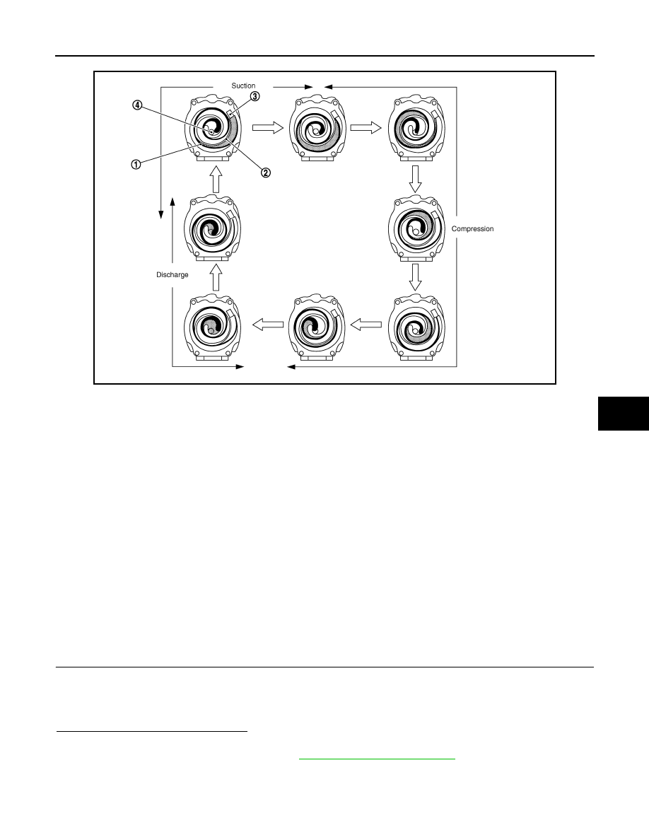
Operation
Suction
As the capacity of the compression chamber, which is created between the orbiting scroll and the fixed scroll,
increases in accordance with the revolution of the orbiting scroll, refrigerant gas is drawn in from the intake
port.
Compression
From the state at which the suction process has been completed, as the revolution of the orbiting scroll
advances further, the capacity of the compression chamber decreases gradually. Consequently, the refrigerant
gas that has been drawn in becomes compressed gradually and is sent to the center of the fixed scroll. The
compression of the refrigerant gas is completed when the orbiting scroll completes approximately 2 revolu-
tions.
Discharge
When the compression of the refrigerant gas is completed and the refrigerant pressure becomes high, the
refrigerant gas discharges through the discharge port located in the center of the fixed scroll by pushing the
discharge valve.
Component Function Check
INFOID:0000000004215382
1.
CONFIRM SYMPTOM BY PERFORMING THE FOLLOWING OPERATIONAL CHECK
1. Turn ignition switch ON (READY).
2. Press AUTO switch and A/C switch.
3. Each switch indicator will turn ON. Confirm that the electric compressor operate. (Discharge air and
blower speed will depend on ambient, in-vehicle and set temperatures.)
Does the electric compressor operate?
YES
>> END.
NO
>> Go to Diagnosis Procedure. Refer to
.
JPIIA0055GB
1.
Orbiting scroll
2.
Fixed scroll
3.
Suction port
4.
Discharge port