Nissan Altima HL32 Hybrid. Manual - part 509


  Index      Nissan     Nissan Altima HL32 Hybrid (2009 year) - Service and Repair Manual


Search            


Content   ..  507  508  509  510   ..


Nissan Altima HL32 Hybrid. Manual - part 509


B263D B263E, B263F, B2656 INTAKE DOOR MOTOR

HAC-57

< COMPONENT DIAGNOSIS >

[AUTOMATIC AIR CONDITIONER]

C

D

E

F

G

H

J

K

L

M

A

B

HAC

N

O

P

Is the inspection result normal?

YES

>> GO TO 3.

NO

>> Replace auto amp. Refer to 

VTL-8, "Removal and Installation"

.

3.

CHECK SIGNAL FOR AUTO AMP. 

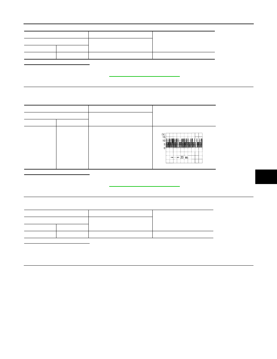
Confirm A/C LAN signal between auto amp. harness connector M37 terminal 3 and ground using an oscillo-

scope.

Is the inspection result normal?

YES

>> GO TO 4.

NO

>> Replace auto amp. Refer to 

VTL-8, "Removal and Installation"

.

4.

CHECK POWER SUPPLY FOR INTAKE DOOR MOTOR

Check voltage between intake door motor harness connector M126 terminal 3 and ground.

Is the inspection result normal?

YES

>> GO TO 5.

NO

>> Repair harness or connector.

5.

CHECK SIGNAL FOR INTAKE DOOR MOTOR

Confirm A/C LAN signal between intake door motor harness connector M126 terminal 1 and ground using an

oscilloscope.

(+)

(

−)

Voltage

Auto amp.

Connector

Terminal

M37

20

Ground

Battery voltage

(+)

(

−)

Voltage

Auto amp.

Connector

Terminal

M37

3

Ground

SJIA1453J

(+)

(

−)

Voltage

Intake door motor

Connector

Terminal

M126

3

Ground

Battery voltage

HAC-58

< COMPONENT DIAGNOSIS >

[AUTOMATIC AIR CONDITIONER]

B263D B263E, B263F, B2656 INTAKE DOOR MOTOR

Is the inspection result normal?

YES

>> GO TO 6.

NO

>> Repair harness or connector.

6.

CHECK INTAKE DOOR MOTOR GROUND CIRCUIT

1. Turn ignition switch OFF.

2. Disconnect intake door motor connector.

3. Check continuity between intake door motor harness connector M126 terminal 2 and ground.

Is the inspection result normal?

YES

>> Replace intake door motor. Refer to 

VTL-16, "Removal and Installation"

.

NO

>> Repair harness or connector.

(+)

(

−)

Voltage

Intake door motor

Connector

Terminal

M126

1

Ground

SJIA1453J

Intake door motor

Continuity

Connector

Terminal

M126

2

Ground

Continuity should exist

B2640, B2641, B2642 ELECTRIC COMPRESSOR

HAC-59

< COMPONENT DIAGNOSIS >

[AUTOMATIC AIR CONDITIONER]

C

D

E

F

G

H

J

K

L

M

A

B

HAC

N

O

P

B2640, B2641, B2642 ELECTRIC COMPRESSOR

Description

INFOID:0000000004215338

The inverter monitors power voltage from the main battery in the circuit. It stops compressor control and out-

puts the DTC when the monitored voltage is outside the specified range. The output DTC of B2640 and B2641

are memorized only present trouble. On B2642, compressor control may not resume unless the ignition switch

is turned OFF and waiting for 10 minutes.

CAUTION:

• Wear electrically insulated gloves and pull out the service plug grip before inspection as procedures

may require disconnecting high-voltage connectors. Be sure to carry the removed service plug grip

because other workers may install it by mistake.

• Do not touch the high-voltage connectors or terminals for 10 minutes after the service plug grip is

removed.

NOTE:

The hybrid control system and air conditioning system output DTCs separately. Inspect DTCs following the

flow chart for the hybrid control system first if any DTCs from those systems are output simultaneously.

DTC Logic

INFOID:0000000004215339

DTC DETECTION LOGIC

DTC CONFIRMATION PROCEDURE

1.

PRECONDITIONING

If DTC Confirmation Procedure has been previously conducted, always turn ignition switch OFF and wait at

least 10 seconds before conducting the next test.

>> GO TO 2.

2.

PERFORM DTC CONFIRMATION PROCEDURE

1. Turn ignition switch ON (READY) and wait at least 5 seconds.

2. Check DTC.
Is DTC detected?

YES

>> Go to Diagnosis Procedure. 

HAC-59, "Diagnosis Procedure"

.

NO

>> END.

Diagnosis Procedure

INFOID:0000000004215340

CAUTION:

• Wear electrically insulated gloves and pull out the service plug grip before inspection as procedures

may require disconnecting high-voltage connectors. Be sure to carry the removed service plug grip

because other workers may install it by mistake.

• Do not touch the high-voltage connectors or terminals for 10 minutes after the service plug grip is

removed.

1.

CHECK CAN COMMUNICATION

Use the CONSULT-III to check if the CAN Communication System is functioning normally.
Is DTC detected?

YES

>> Check CAN communication. Refer to 

LAN-16, "Trouble Diagnosis Flow Chart"

.

NO

>> GO TO 2.

DTC No.

Trouble Diagnosis Name

DTC Detecting Condition

Possible Cause

B2640

MAIN VOLT MIN

After READY and A/C ON

• Harness or connector between electric com-

pressor and MG ECU

• Electric compressor
• HV ECU
• MG  ECU
• CAN communication system

B2641

MAIN VOLT MAX

After READY and A/C ON

B2642

MAIN VOLT MALFNCTN

After READY and A/C ON

HAC-60

< COMPONENT DIAGNOSIS >

[AUTOMATIC AIR CONDITIONER]

B2640, B2641, B2642 ELECTRIC COMPRESSOR

2.

CHECK DIAGNOSTIC TROUBLE CODE (HV ECU)

Check if DTCs for the hybrid control system are output using the CONSULT-III.
Is DTC detected?

YES

>> GO TO 3.

NO

>> Go to HV ECU. Refer to 

HBC-9, "Work Flow"

.

3.

INSPECT ELECTRIC VEHICLE FUSE

1. Turn ignition switch OFF.

2. Remove the service plug grip.

CAUTION:

• Be sure to wear insulated gloves.

• Do not touch the high-voltage connectors or terminals for 10 minutes after the service plug grip

is removed.

NOTE:

Do not start the engine with the service plug grip removed because it may cause a malfunction.

3. Remove the connector cover assembly.

CAUTION:

Be sure to wear insulated gloves.

NOTE:

Be sure to prevent foreign objects or water from entering the MG ECU.

4. Check that bolts A and B are tightened securely.

5. Measure the resistance according to the value(s) in the table below.

Is the inspection result normal?

YES

>> GO TO 4.

NO

>> Replace electric vehicle fuse.

4.

INSPECT MG ECU

CAUTION:

• Be sure to wear insulated gloves.

• Do not touch the high-voltage connectors or terminals for 10 minutes after the service plug grip is

removed.

JPIIA0313GB

Electric compressor

Condition

Resistance (

Ω)

A

B

Always

Below 1.0


Content   ..  507  508  509  510   ..