Nissan Altima HL32 Hybrid. Manual - part 496
INSPECTION AND ADJUSTMENT
HAC-5
< BASIC INSPECTION >
[AUTOMATIC AIR CONDITIONER]
C
D
E
F
G
H
J
K
L
M
A
B
HAC
N
O
P
INSPECTION AND ADJUSTMENT
Description & Inspection
INFOID:0000000004215295
DESCRIPTION
The purpose of the operational check is to check if the individual system operates properly.
INSPECTION PROCEDURE
Memory Function
1. Turn temperature control dial (driver side) clockwise until 32
°C (90°F) is displayed.
2. Press OFF switch.
3. Turn ignition switch OFF.
4. Turn ignition switch ON (READY).
5. Press AUTO switch.
6. Confirm that the set temperature remains at previous temperature.
7. Press OFF switch.
If NG, go to trouble diagnosis procedure for
HAC-156, "Inspection procedure"
If OK, continue the check.
Blower
1. Turn fan control dial clockwise. Blower should operate on low speed.
2. Turn fan control dial clockwise again, and continue checking blower speed and fan symbol until all speeds
are checked.
3. Leave blower on max. speed.
If NG, go to trouble diagnosis procedure for
.
If OK, continue the check.
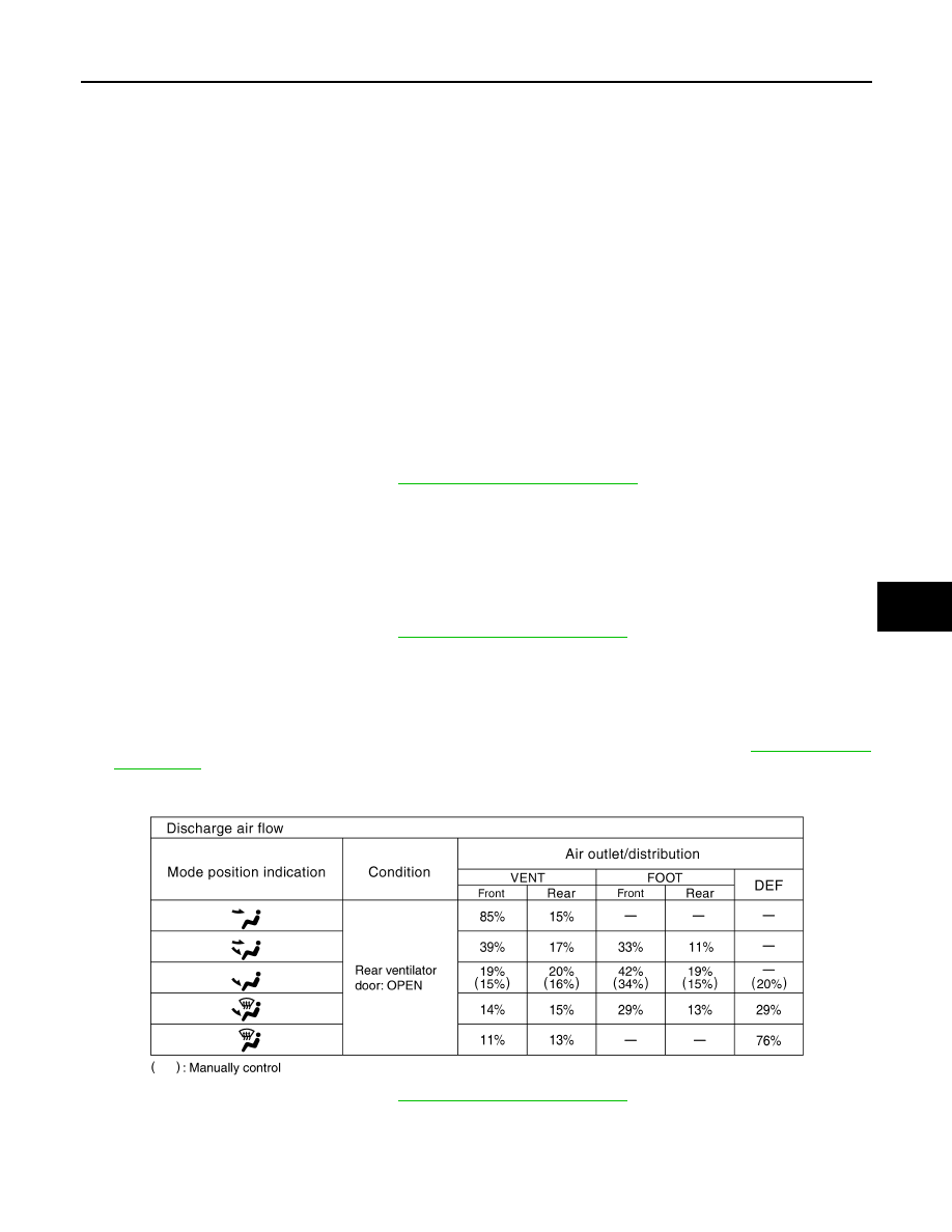
Discharge Air
1. Press MODE switch and DEF switch.
2. Each position indicator should illuminate.
3. Confirm that discharge air comes out according to the air distribution table. Refer to
.
If NG, go to trouble diagnosis procedure for
.
If OK, continue the check.
NOTE:
Confirm that the intake door position is at FRE when the D/F or DEF is selected.
Intake Air
Conditions
: After READY
JPIIA0232GB