Nissan Altima HL32 Hybrid. Manual - part 413


  Index      Nissan     Nissan Altima HL32 Hybrid (2009 year) - Service and Repair Manual


Search            


Content   ..  411  412  413  414   ..


Nissan Altima HL32 Hybrid. Manual - part 413


EXL-52

< COMPONENT DIAGNOSIS >

OPTICAL SENSOR

3.

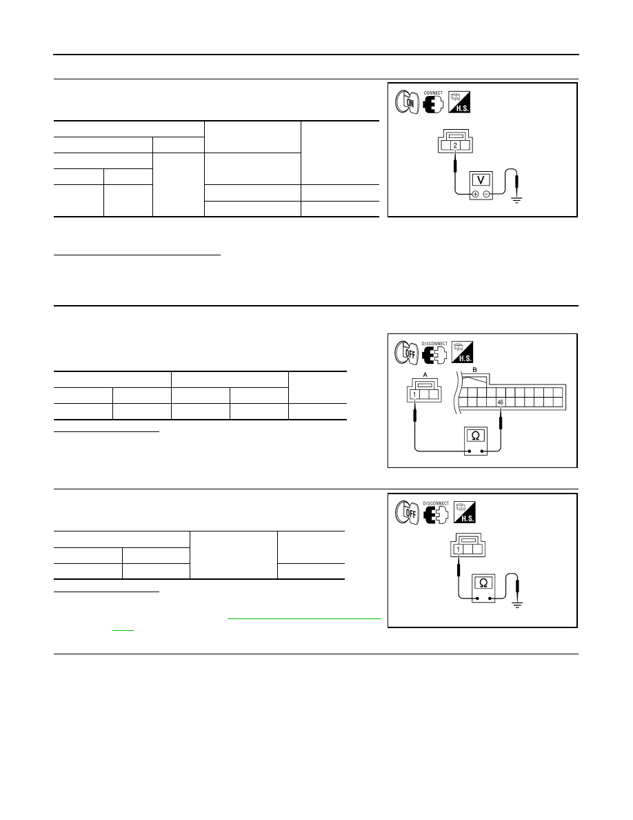
CHECK OPTICAL SENSOR SIGNAL OUTPUT

 With the optical sensor illuminating, check voltage between the opti-

cal sensor harness connector and ground.

*: Illuminate the optical sensor. The value may be less than the standard if brightness
is weak.

Is the measurement value normal?

YES

>> GO TO 7

NO

>> Replace the optical sensor.

4.

CHECK OPTICAL SENSOR POWER SUPPLY FOR OPEN CIRCUIT

1. Turn the ignition switch OFF.

2. Disconnect the optical sensor connector and BCM connector.

3. Check continuity between the optical sensor harness connector

and the BCM harness connector.

Does continuity exist?

YES

>> GO TO 5

NO

>> Repair the harnesses or connectors.

5.

CHECK OPTICAL SENSOR POWER SUPPLY FOR SHORT CIRCUIT

Check the continuity between the optical sensor harness connector

and the ground.

Does continuity exist?

YES

>> Repair the harnesses or connectors.

NO

>> Replace BCM. Refer to 

BCS-87, "Removal and Installa-

tion"

 .

6.

CHECK OPTICAL SENSOR GROUND FOR OPEN CIRCUIT

1. Turn the ignition switch OFF.

2. Disconnect the optical sensor connector and BCM connector.

Terminals

Condition

Voltage

(+)

(

−)

Optical sensor

Ground

Optical sensor

Connector

Terminal

M66

2

When illuminating

3.1V or more *

When shutting off light

0.6V or less

ALLIA0132ZZ

A

B

Continuity

Connector

Terminal

Connector

Terminal

M66

1

M18

46

Yes

ALLIA0133ZZ

Optical sensor

Ground

Continuity

Connector

Terminal

M66

1

No

ALLIA0134ZZ

OPTICAL SENSOR

EXL-53

< COMPONENT DIAGNOSIS >

C

D

E

F

G

H

I

J

K

M

A

B

EXL

N

O

P

3. Check continuity between the optical sensor harness connector

and the BCM harness connector.

Does continuity exist?

YES

>> Replace BCM. Refer to 

BCS-87, "Removal and Installa-

tion"

 .

NO

>> Repair the harnesses or connectors.

7.

CHECK OPTICAL SENSOR SIGNAL FOR OPEN CIRCUIT 

1. Turn the ignition switch OFF.

2. Disconnect the optical sensor connector and BCM connector.

3. Check continuity between the optical sensor harness connector

and the BCM harness connector.

Does continuity exist?

YES

>> GO TO 8

NO

>> Repair the harnesses or connectors.

8.

CHECK OPTICAL SENSOR SIGNAL FOR SHORT CIRCUIT

Check the continuity between the optical sensor harness connector

and the ground.

Does continuity exist?

YES

>> Repair the harnesses or connectors.

NO

>> Replace BCM. Refer to 

BCS-87, "Removal and Installa-

tion"

 .

A

B

Continuity

Connector

Terminal

Connector

Terminal

M66

3

M18

45

Yes

ALLIA0135ZZ

Optical sensor

BCM

Continuity

Connector

Terminal

Connector

Terminal

M66

2

M18

21

Yes

ALLIA0136ZZ

Optical sensor

Ground

Continuity

Connector

Terminal

M66

2

No

ALLIA0137ZZ

EXL-54

< COMPONENT DIAGNOSIS >

HEADLAMP

HEADLAMP

Wiring Diagram 

INFOID:0000000004216406

ABLWA0236GB

HEADLAMP

EXL-55

< COMPONENT DIAGNOSIS >

C

D

E

F

G

H

I

J

K

M

A

B

EXL

N

O

P

ABLIA0835GB


Content   ..  411  412  413  414   ..