Nissan Altima HL32 Hybrid. Manual - part 386


  Index      Nissan     Nissan Altima HL32 Hybrid (2009 year) - Service and Repair Manual


Search            


Content   ..  384  385  386  387   ..


Nissan Altima HL32 Hybrid. Manual - part 386


EM-58

< ON-VEHICLE REPAIR >

[QR25DE]

TIMING CHAIN

9. Install IVT cover with the following procedure:
a. Install IVT solenoid valve to IVT cover.
b. Install new O-ring to front cover.
c.

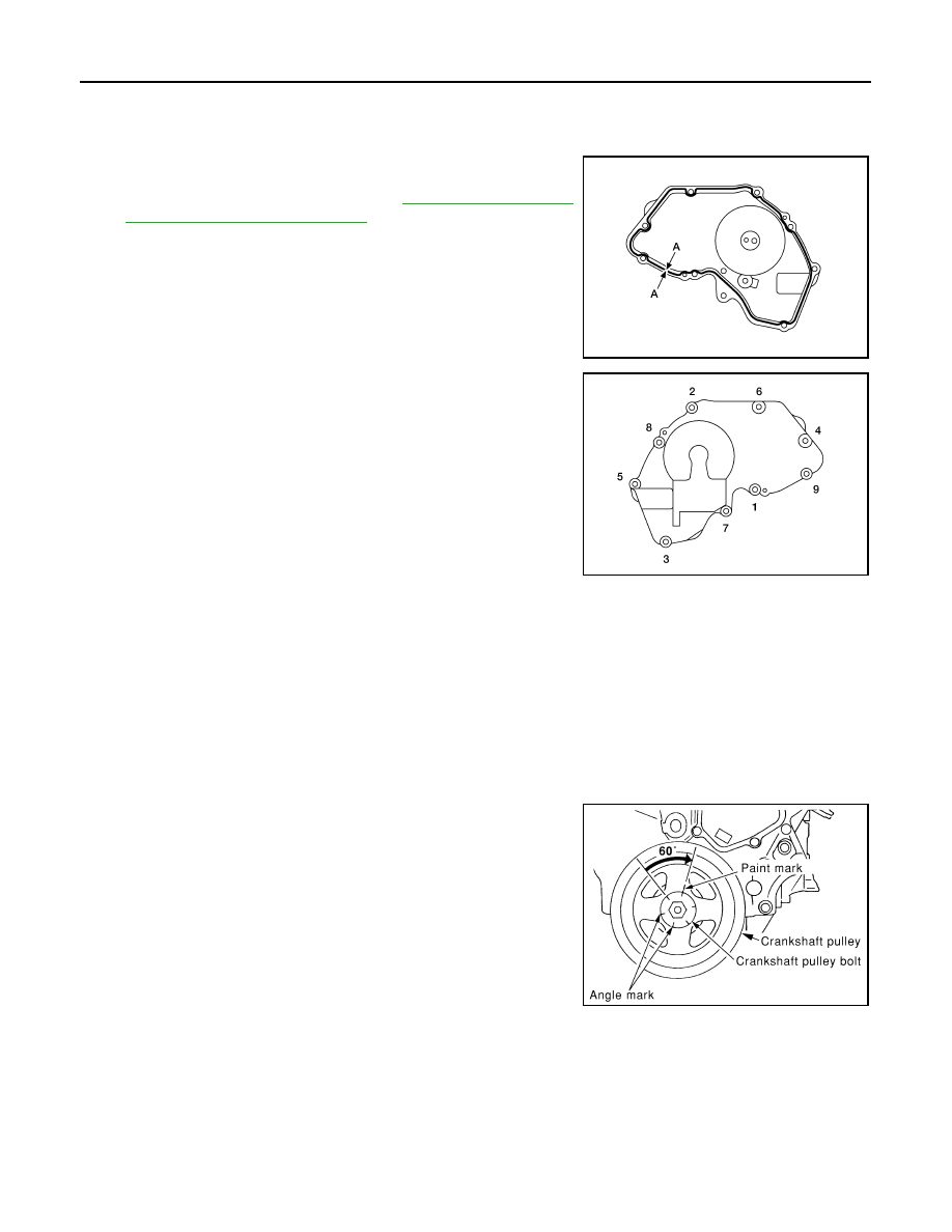
Apply Silicone RTV Sealant to the IVT cover as shown.

• Apply Genuine Silicone RTV Sealant or equivalent, to posi-

tions specified as shown. Refer to 

GI-15, "Recommended

Chemical Products and Sealants"

d. Tighten the IVT cover bolts in the numerical order as shown.

10. Insert crankshaft pulley by aligning with crankshaft key. 

• Tap its center with a plastic hammer to insert. 

• Do not tap the belt hook.

11. Tighten crankshaft pulley bolts.

• Secure crankshaft pulley with tool to tighten the bolt.

• Perform angle tightening with the following procedure:

a. Apply new engine oil to threads and seat surfaces of bolts.
b. Tighten to initial specifications:·

c.

Apply a paint mark on the front cover, mating with any one of six

easy to recognize stamp marks on bolt flange. 

d. Turn crankshaft pulley bolt another 60

° to 66° degrees [Target:

60

° degrees].

• Check vertical mounting angle with movement of one stamp

mark.

12. Installation of the remaining components is in the reverse order

of removal.

Diameter (A)

: 3.4 - 4.4 mm (0.134 - 0.173 in)

ALBIA0193ZZ

ALBIA0192ZZ

Crankshaft bolt

: 42.1 N·m (4.3 kg-m, 31 ft-lb)

SBIA0268E

OIL SEAL

EM-59

< ON-VEHICLE REPAIR >

[QR25DE]

C

D

E

F

G

H

I

J

K

L

M

A

EM

N

P

O

OIL SEAL

Removal and Installation of Valve Oil Seal

INFOID:0000000004211253

REMOVAL

1. Remove camshaft. Refer to 

EM-40, "Removal and Installation"

.

2. Remove valve lifter. Refer to 

EM-40, "Removal and Installation"

.

3. Rotate crankshaft, and set piston whose oil seal is to removed to top dead center. This prevents valve

from dropping inside cylinder.

CAUTION:

When rotating crankshaft, be careful to avoid scarring the front cover with the timing chain.

4. Remove valve collet, valve spring retainer and valve spring using Tool.

5. Remove valve oil seal using Tool.

INSTALLATION

1. Apply new engine oil to new valve oil seal joint surface and seal lip.
2. Press in valve oil seal to the position shown using Tool.

3. Installation of the remaining components in the reverse order of removal.

Removal and Installation of Front Oil Seal

INFOID:0000000004211254

REMOVAL

1. Remove the following parts:

• Engine under cover using power tools.

Tool number

: KV10116200 (J-26336-B)
: KV10115900 (J-26336-20)

WBIA0477E

Tool number

: KV10107902 (J-38959)

WBIA0478E

Oil seal installed height : 12.1 mm (0.476 in)

Tool number

: KV10115600 (J-38958)

AWBIA0019ZZ

EM-60

< ON-VEHICLE REPAIR >

[QR25DE]

OIL SEAL

• Drive belts. Refer to 

EM-14

.

• Crankshaft pulley. Refer to 

EM-51

.

2. Remove front oil seal from front cover.

CAUTION:

Be careful not to scratch front cover.

INSTALLATION

1. Apply new engine oil to new oil seal and install it using a suitable

tool.

• Install new oil seal in the direction shown.

2. Installation of the remaining components is in reverse order of removal. 

Removal and Installation of Rear Oil Seal

INFOID:0000000004211255

REMOVAL

1. Remove the transaxle. Refer to 

TM-36, "Removal and Installation"

.

2. Remove drive plate (CVT).
3. Remove rear oil seal using suitable tool.

CAUTION:

 Be careful not to scratch rear oil seal retainer.

INSTALLATION

1. Apply new engine oil to new oil seal and install it using a suitable drift.

SBIA0266E

SEM715A

WBIA0204E

OIL SEAL

EM-61

< ON-VEHICLE REPAIR >

[QR25DE]

C

D

E

F

G

H

I

J

K

L

M

A

EM

N

P

O

• Install new oil seal in the direction shown.

• Press fit new oil seal straight using a suitable drift, to avoid

causing burrs or tilting.

• Press in the new oil seal to the specified depth as shown.

2. Installation of the remaining components is in the reverse order of removal.

SEM715A

SBIA0280E

SBIA0281E


Content   ..  384  385  386  387   ..