Nissan Altima HL32 Hybrid. Manual - part 120


  Index      Nissan     Nissan Altima HL32 Hybrid (2009 year) - Service and Repair Manual


Search            


Content   ..  118  119  120  121   ..


Nissan Altima HL32 Hybrid. Manual - part 120


DIAGNOSIS SYSTEM (VDC/TCS/ABS CONTROL UNIT)

BRC-45

< FUNCTION DIAGNOSIS >

[VDC/TCS/ABS]

C

D

E

G

H

I

J

K

L

M

A

B

BRC

N

O

P

DIAGNOSIS SYSTEM (VDC/TCS/ABS CONTROL UNIT)

CONSULT-III Function

INFOID:0000000004212634

DIAGNOSIS SYSTEM

Description

When troubleshooting a vehicle with the diagnosis system, the only difference from the usual troubleshooting

procedure is connecting the CONSULT-III to the vehicle and reading various data output from the vehicle

′s

brake ECU. 

The brake ECU records DTCs when the computer detects a malfunction in the computer itself or in its circuits.

To check for DTCs, activate the various actuators, and check the Freeze Frame Data and Data List.
1. Check the auxiliary battery voltage.

If the voltage is below 11 V, recharge the auxiliary battery before proceeding to the next step.

2. Check the DLC3.

The ECU uses ISO 15765-4 for communication. The terminal arrangement of the DLC3 complies with

SAE J1962 and matches the ISO 15765-4 format.

If the result is not as specified, the DLC3 may have a malfunction. Repair or replace the harness and con-

nector.

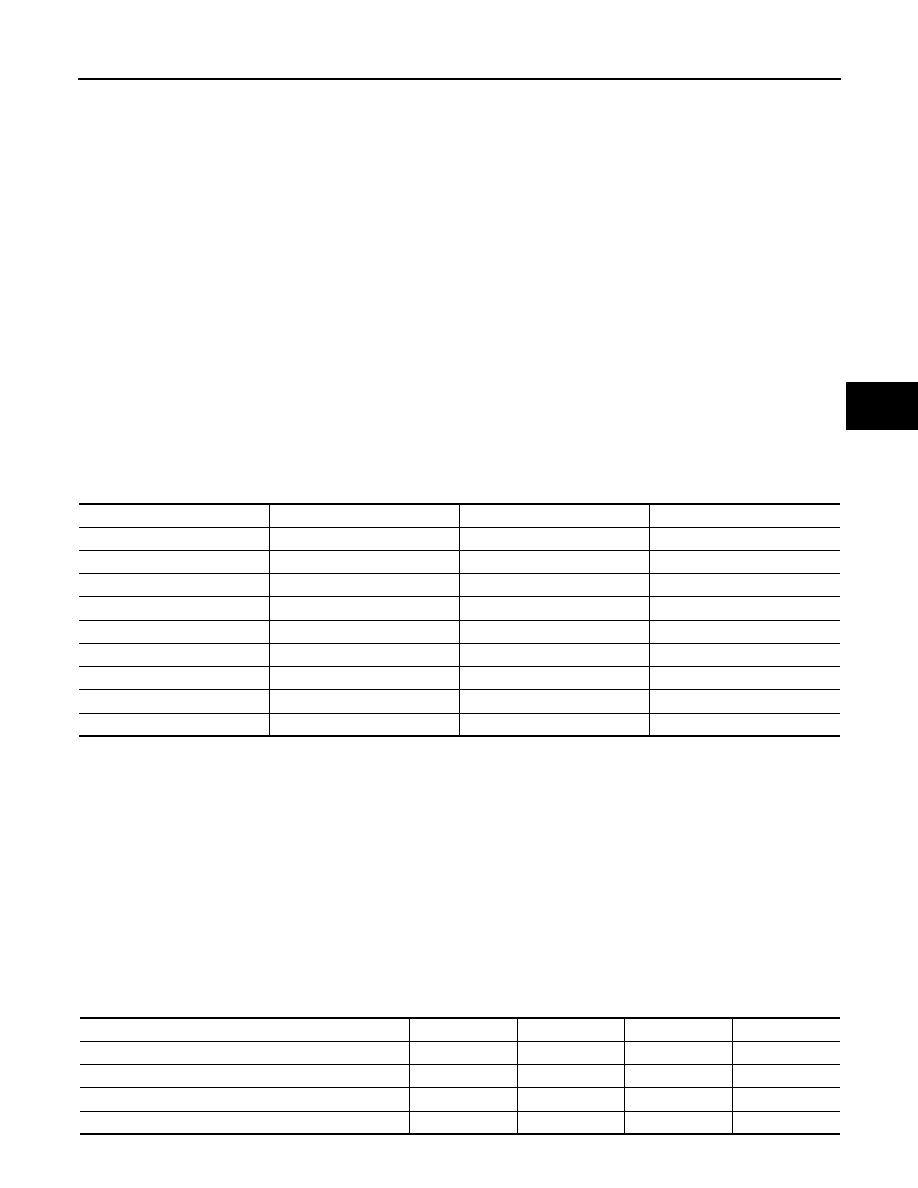
Verify the conditions listed in the table below.

*: Before measuring the resistance, leave the vehicle as is for at least 1 minute and do not operate the ignition switch, any other
switches or the doors.

NOTE:

• Connect the cable of the CONSULT-III to the DLC3, turn the ignition switch ON and attempt to use the tester.

If the display indicates that a communication error has occurred, there is a problem either with the vehicle or

with the tester.

• If communication is normal when the tester is connected to another vehicle, inspect the DLC3 on the original

vehicle.

• If communication is still not possible when the tester is connected to another vehicle, the problem may be in

the tester itself. CONSULT-III the Service Department listed in the tester operator

′s manual.

Diagnosis

1. If the brake ECU detects a malfunction, the ABS warning lamp, brake warning lamp, Electronically Con-

trolled Brake warning lamp, VDC warning lamp, and SLIP indicator lamp will come ON.

The table below indicates which lamps will come ON when there is a malfunction in a particular function.

×: Light ON –: Light OFF

Standard voltage : 11 to 14 V

Symbols (Terminal No.)

Terminal description

Condition

Specified condition

7 – 5

Bus “+” line

During transmission

Pulse generation

4 – Ground

Chassis ground

Always

Below 1 

5 – Ground

Signal ground

Always

Below 1 

16 – Ground

Battery positive

Always

11 to 14 V

6 – 14

CAN communication line

Ignition switch OFF*

54 to 69 

6 – 4

CAN-H line

Ignition switch OFF*

200 

Ω or higher

14 – 4

CAN-L line

Ignition switch OFF*

200 

Ω or higher

6 – 16

CAN-H line

Ignition switch OFF*

6 k

Ω or higher

14 – 16

CAN-L line

Ignition switch OFF*

6 k

Ω or higher

Item / Trouble area

ABS

EBD

TCS

VDC

ABS warning lamp

×

×

Brake warning lamp

×

Electronically Controlled Brake warning lamp

×

×

VDC warning lamp

×

×

×

×

BRC-46

< FUNCTION DIAGNOSIS >

[VDC/TCS/ABS]

DIAGNOSIS SYSTEM (VDC/TCS/ABS CONTROL UNIT)

Warning Lamp and Indicator Lamp Check

1. Release the parking brake.

CAUTION:

When replacing the parking brake, move the shift lever to the P position for safety.

NOTE:

When the parking brake is applied or the level of the brake fluid is low, the brake warning lamp comes on.

2. When the ignition switch is turned ON, check that the ABS warning, brake warning, Electronically Con-

trolled Brake warning, and SLIP indicator lamps come ON and remain in until the ignition switch is turned

ON (READY).

NOTE:

If the warning lamp and indicator lamp check result is not normal, proceed to troubleshooting for the ABS

warning, brake warning, Electronically Controlled Brake warning, VDC warning, and SLIP indicator lamp

circuits.

If the indicator remains ON, proceed to troubleshooting for the lamp circuit below.

Symptom Simulation

NOTE:

The most difficult case in troubleshooting is when no symptoms occur. In such cases, a thorough customer

problem analysis must be carried out. Then the same or similar conditions and environment in which the prob-

lem occurred in the customer

′s vehicle should be reproduced. No matter how experienced or skilled a techni-

cian may be, if he proceeds to troubleshoot without confirming the problem symptoms, he will likely overlook

something important and make a wrong guess at some points in the repair operation. This leads to a standstill

in troubleshooting.
1. Vibration method: When vibration seems to be the major cause.

NOTE:

Perform the simulation method only during the primary check period (for approximately 6 seconds after

the ignition switch is turned ON.)

a. Slightly vibrate the part of the sensor considered to be the problem cause with your fingers and check

whether the malfunction occurs.

b. Slightly shake the connector vertically and horizontally.

NOTE:

Shaking the relays too strongly may result in open relays.

c.

Slightly shake the wire harness vertically and horizontally. The connector joint and fulcrum of the vibration

are the major areas to be checked thoroughly.

FREEZE FRAME DATA

Freeze Frame Data/ Information

1. Whenever an ABS DTC is detected, the brake ECU stored the current vehicle (sensor) state as Freeze

Frame Data.

2. The brake ECU stores the number of times (maximum: 31) the ignition switch has been turned from off to

ON since the last time the ABS was activated.

3. For DTCs memorized in the brake ECU, information (INF) codes that are contained in the Freeze Frame

Data can be displayed on the CONSULT-III.

NOTE:

• However, if the vehicle is stopped or at a low speed [7 km/h (4.3 MPH) or less], or if a DTC is detected,

the brake ECU will stop counting the number. 

• Freeze Frame Data at the time the ABS operates:

The brake ECU stores and updates data whenever the ABS system operates.

When the ECU stores data at time a DTC is detected, the data stored during ABS operation is erased.

• Freeze Frame Data at the time a DTC is detected:

Trouble area

Reference page

ABS warning lamp circuit

BRC-172, "Description"

Brake warning lamp circuit

BRC-177, "Description"

Electronically Controlled Brake warning lamp circuit

BRC-182, "Description"

VDC warning lamp circuit

BRC-175, "Description"

SLIP indicator lamp circuit

BRC-185, "Description"

DIAGNOSIS SYSTEM (VDC/TCS/ABS CONTROL UNIT)

BRC-47

< FUNCTION DIAGNOSIS >

[VDC/TCS/ABS]

C

D

E

G

H

I

J

K

L

M

A

B

BRC

N

O

P

When the brake ECU stores data at the time a DTC is detected, no updates will be performed until the

data is cleared.

Check Freeze Frame Data and Information

Tester display

Measurement item

Reference value

VHCL BODY SPD

Vehicle speed reading

Min

0 km/h (0 MPH)

Max

326.4 km/h (202 MPH)

STP

Stop lamp switch signal

Stop lamp switch ON

ON

Stop lamp switch OFF

OFF

IG ON COUNT

Number of operations of ignition 
switch ON after storing Freeze 
Frame Data

0 to 31

MC PRESS SEN 1

Master cylinder pressure sen-
sor reading

Brake pedal released

0.3 to 0.9 V

MC PRESS SEN 2

Master cylinder pressure sen-
sor change

Min

− 30 MPa/s

Max

225 MPa/s

YAW RATE SEN

Yaw rate sensor reading

Min

− 128 deg/s

Max

127 deg/s

ST ANG SEN

Steering angle sensor reading

Left turn

Increase

Right turn

Decrease

DECEL G SEN

Decel G sensor reading

Min

− 25.11 m/s

2

Max

24.91 m/s

2

BUZZER

Brake warning buzzer signal

Brake warning buzzer ON

ON

Brake warning buzzer OFF

OFF

ACC VALU RATE

Accelerator operating angle

Min

0%

Max

128%

PKB

Parking brake switch signal

Parking brake switch ON

ON

Parking brake switch OFF

OFF

FR SEN SIG

FR wheel speed

Min

0 km/h (0 MPH)

Max

326.4 km/h (202 MPH)

FL SEN SIG

FL wheel speed

Min

0 km/h (0 MPH)

Max

326.4 km/h (202 MPH)

RR SEN SIG

RR wheel speed

Min

0 km/h (0 MPH)

Max

326.4 km/h (202 MPH)

RL SEN SIG

RL wheel speed

Min

0 km/h (0 MPH)

Max

326.4 km/h (202 MPH)

SIDE G SEN

Side G sensor reading

Min

− 25.11 m/s

2

Max

24.91 m/s

2

SFT LVR INFOR

Shift lever position information

FAIL
1st
2nd
3rd
4th
5th
6th/B
D/M
P, N
R

BRC-48

< FUNCTION DIAGNOSIS >

[VDC/TCS/ABS]

DIAGNOSIS SYSTEM (VDC/TCS/ABS CONTROL UNIT)

OPE SYSTEM

Operated system status

ABS activated

ABS

VDC activated

VDC

TCS activated

TCS

No system activated

NON

System prohibited

SYS

FREE TRIG EL

Elapsed time after freeze trigger

Min

0 ms

Max

500 ms

FIRST DTC

Freeze frame DTC

Displays output DTC

STRK SEN 1

Stroke sensor reading

Min

0 V

Max

5 V

STRK SEN 2

Stroke sensor 2 reading

Min

0 V

Max

5 V

FR WC PRESS

FR wheel cylinder pressure 
sensor reading

Min

0 V

Max

5 V

FL WC PRESS

FL wheel cylinder pressure sen-
sor reading

Min

0 V

Max

5 V

RR WC PRESS

RR wheel cylinder pressure 
sensor reading

Min

0 V

Max

5 V

RL WC PRESS

RL wheel cylinder pressure 
sensor reading

Min

0 V

Max

5 V

ACCUM SEN

Accumulator pressure sensor 
reading

Min

0 V

Max

5 V

MC PRESS SEN 2

Master cylinder pressure sen-
sor reading

Brake pedal released

0.3 to 0.9 V

MTT

Motor relay voltage value

Min

0 V

Max

20 V

SLAFR VALUE

Linear solenoid (SLAFR) cur-
rent

Min

0 A

Max

3 A

SLAFL VALUE

Linear solenoid (SLAFL) cur-
rent

Min

0 A

Max

3 A

SLARR VALUE

Linear solenoid (SLARR) cur-
rent

Min

0 A

Max

3 A

SLARL VALUE

Linear solenoid (SLARL) cur-
rent

Min

0 A

Max

3 A

SLRFR VALUE

Linear solenoid (SLRFR) cur-
rent

Min

0 A

Max

3 A

SLRFL VALUE

Linear solenoid (SLRFL) cur-
rent

Min

0 A

Max

3 A

SLRRR VALUE

Linear solenoid (SLRRR) cur-
rent

Min

0 A

Max

3 A

SLRRL VALUE

Linear solenoid (SLRRL) cur-
rent

Min

0 A

Max

3 A

FR OIL PRESS

FR wheel target oil pressure 
reading

Min

0 MPa

Max

20 MPa

Tester display

Measurement item

Reference value


Content   ..  118  119  120  121   ..