Content .. 1088 1089 1090 1091 ..
Nissan Altima HL32 Hybrid. Manual - part 1090
WCS-14
< FUNCTION DIAGNOSIS >
DIAGNOSIS SYSTEM (METER)
SELF-DIAG RESULTS
Display Item List
.
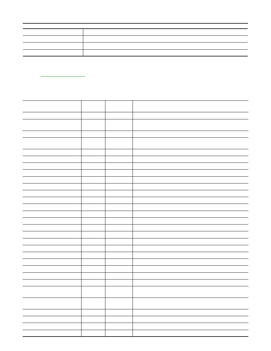
DATA MONITOR
Display Item List
X: Applicable
METER/M&A diagnosis mode
Description
SELF-DIAG RESULTS
Displays combination meter self-diagnosis results.
DATA MONITOR
Displays combination meter input/output data in real time.
CAN DIAG SUPPORT MNTR
The result of transmit/receive diagnosis of CAN communication can be read.
Display item [Unit]
MAIN
SIGNALS
SELECTION
FROM MENU
Description
SPEED METER [km/h] or [mph]
X
X
Displays the value of vehicle speed signal.
SPEED OUTPUT [km/h] or [mph]
X
X
Displays the value of vehicle speed signal, which is transmitted to
each unit with CAN communication.
ODO OUTPUT
X
Displays the value, which is calculated by vehicle speed signal.
FUEL METER [lit.]
X
X
Displays the value, which processes a resistance signal from fuel
gauge.
ABS W/L [ON/OFF]
X
Displays [ON/OFF] condition of ABS warning lamp.
VDC/TCS IND [ON/OFF]
X
Displays [ON/OFF] condition of VDC/TCS OFF indicator lamp.
SLIP IND [ON/OFF]
X
Displays [ON/OFF] condition of SLIP indicator lamp.
HEV BRAKE W/L [ON/OFF]
X
Displays [ON/OFF] condition of HEV brake warning lamp.*
DOOR W/L [ON/OFF]
X
Displays [ON/OFF] condition of door warning lamp.
TRUNK/GLAS-H [ON/OFF]
X
Displays [ON/OFF] condition of trunk warning lamp.
HI-BEAM IND [ON/OFF]
X
Displays [ON/OFF] condition of high beam indicator.
TURN IND [ON/OFF]
X
Displays [ON/OFF] condition of turn indicator.
OIL W/L [ON/OFF]
X
Displays [ON/OFF] condition of oil pressure warning lamp.
MIL [ON/OFF]
X
Displays [ON/OFF] condition of malfunction indicator lamp.
CRUISE IND [ON/OFF]
X
Displays [ON/OFF] condition of CRUISE indicator.
SET IND [ON/OFF]
X
Displays [ON/OFF] condition of SET indicator.
FUEL W/L [ON/OFF]
X
Displays [ON/OFF] condition of low-fuel warning lamp.
WASHER W/L [ON/OFF]
X
Displays [ON/OFF] condition of low-washer fluid warning lamp.
AIR PRES W/L [ON/OFF]
X
Displays [ON/OFF] condition of tire pressure warning lamp.
KEY G W/L [ON/OFF]
X
Displays [ON/OFF] condition of key warning lamp.
PUSH ENG IND
X
Displays the value of Intelligent Key system message indication.
SHIFT IND [P, R, N, D, L]
X
Displays [P, R, N, D, L] range position of ECVT.
PKB SW [ON/OFF]
X
Displays [ON/OFF] condition of parking brake switch.
BUCKLE SW [ON/OFF]
X
Displays [ON/OFF] condition of seat belt buckle switch LH.
DISTANCE [km] or [mile]
X
Displays the value, which is calculated by vehicle speed signal, fuel
gauge and fuel consumption from ECM.
OUTSIDE TEMP [
°C]
X
Displays the ambient air temperature, which is input from ambient
sensor.
FUEL LOW SIG [ON/FF]
X
Displays [ON/OFF] condition of low-fuel warning signal.
BUZZER [ON/OFF]
X
X
Displays [ON/OFF] condition of buzzer.
ALL POWER METER [kw]
X
Displays the value of power meter.
SOC METER [%]
X
Displays the position of the high voltage battery status meter pointer.