Nissan Altima HL32 Hybrid. Manual - part 1073


  Index      Nissan     Nissan Altima HL32 Hybrid (2009 year) - Service and Repair Manual


Search            


Content   ..  1071  1072  1073  1074   ..


Nissan Altima HL32 Hybrid. Manual - part 1073


TM-10

< FUNCTION DIAGNOSIS >

[HYBRID TRANSAXLE: RE0F01H]

MECHANICAL SYSTEM

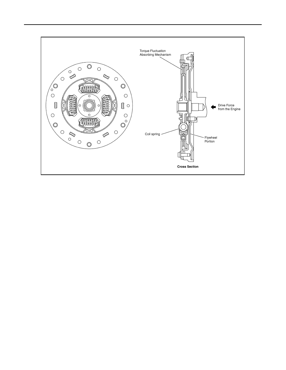
uses a dry-type, single-plate friction material is used. Through the use of the parts, a damper construction that

excels in absorbing the vibrations of the engine motive force has been achieved.

MG1 AND MG2

MG1 and MG2 are located coaxially at each end of the compound gear unit. MG1 connects to the sun gear of

the power split planetary gear, and MG2 connects to the sun gear of the motor speed reduction planetary gear.

NOTE:

Do not disassemble MG1 or MG2 because they are precision components. If a malfunction is found on either

of these components, replace MG1 or MG2 as a complete assembly.

Lubrication Mechanism

INFOID:0000000004212367

• This transaxle is lubricated by a trochoid type oil pump placed on the main shaft.

• Furthermore, it uses a final gear with an oil sling type lubrication mechanism. This construction minimizes

the drive torque of the oil pump, which reduces the drive loss.

JPDIA0091GB

MECHANICAL SYSTEM

TM-11

< FUNCTION DIAGNOSIS >

[HYBRID TRANSAXLE: RE0F01H]

C

E

F

G

H

I

J

K

L

M

A

B

TM

N

O

P

• An oil catch tank is used in this transaxle in order to supply oil in a stable manner. The oil catch tank tempo-

rarily stores the oil that is slung up, and supplies oil to each gear train from there. Furthermore, oil holes are

provided in the oil catch tanks in order to efficiently supply oil to MG1 and MG2.

Shift Control System

INFOID:0000000004212368

SHIFT CONTROL

• A shift position sensor is provided in the transaxle to detect the shift position and sends a corresponding sig-

nal to the HV ECU. Upon receiving this signal, the HV ECU optimally combines the operation of the engine,

MG1 and MG2 in order to produce the respective shift positions (“P”, “R”, “N”, “D” and “B”).

JPDIA0092GB

JPDIA0093GB

TM-12

< FUNCTION DIAGNOSIS >

[HYBRID TRANSAXLE: RE0F01H]

MECHANICAL SYSTEM

• However, because the movement of the wheels must be mechanically locked in the P position, a parking

lock mechanism is used in the transaxle. Therefore, if the driver operates the shift lever to the P position, a

cable and a linkage cause the movement of the transaxle to lock mechanically.

PARKING LOCK MECHANISM

• A mechanical parking lock mechanism has been provided in the compound gear. The engagement of the

parking lock pawl with the parking gear that is integrated with the compound gear locks the movement of the

vehicle.

• When the driver moves the shift lever to the P position, the cable at the shift lever causes the No.1 lever to

rotate. The rotational movement of the No.1 lever causes the parking lock rod to slide and the parking lock

pawl to push up. As a result, the parking lock pawl locks the parking gear.

JPDIA0094GB

JPDIA0095GB

SHIFT LOCK SYSTEM

TM-13

< FUNCTION DIAGNOSIS >

[HYBRID TRANSAXLE: RE0F01H]

C

E

F

G

H

I

J

K

L

M

A

B

TM

N

O

P

SHIFT LOCK SYSTEM

System Diagram

INFOID:0000000004212369

System Description

INFOID:0000000004212370

The selector lever cannot be shifted from “P” position to any other position unless the ignition switch is in the

ON position and the brake pedal is depressed.

Component Parts Location

INFOID:0000000004212371

Component Description

INFOID:0000000004212372

AWDIA0009GB

1.

BCM (view with instrument panel re-
moved) M19

2.

Steering column

3.

Stop lamp switch E38

4.

Shift lock release button

5.

Shift lock solenoid/Detent switch 
(key) 

6.

ECVT device connector M23 

AWDIA0008ZZ


Content   ..  1071  1072  1073  1074   ..