Nissan Altima HL32 Hybrid. Manual - part 1051


  Index      Nissan     Nissan Altima HL32 Hybrid (2009 year) - Service and Repair Manual


Search            


Content   ..  1049  1050  1051  1052   ..


Nissan Altima HL32 Hybrid. Manual - part 1051


ST-2

< SYMPTOM DIAGNOSIS >

NOISE, VIBRATION AND HARSHNESS (NVH) TROUBLESHOOTING

SYMPTOM DIAGNOSIS

NOISE, VIBRATION AND HARSHNESS (NVH) TROUBLESHOOTING

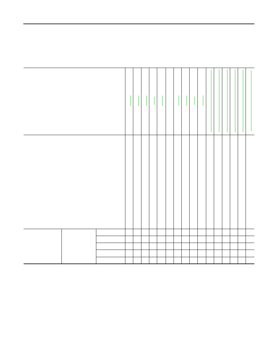
NVH Troubleshooting Chart

INFOID:0000000004212793

Use chart below to help you find the cause of the symptom. If necessary, repair or replace these parts.

×: Applicable

Reference page

ST

-15

ST

-15

ST

-15

ST

-6

ST

-15

ST

-12

ST

-14

ST

-9

ST

-12

F

AX-2, "

NVH T

rou

bl

es

ho

ot

in

g Cha

rt

"

FSU-2,

 "

NVH T

ro

ub

les

h

oot

in

g Ch

art

"

WT

-57,

 "

NVH T

ro

ub

les

ho

ot

ing

 Ch

art

"

WT

-57,

 "

NVH T

ro

ub

les

ho

ot

ing

 Ch

art

"

F

AX-2, "

NVH T

rou

bl

es

ho

ot

in

g Cha

rt

"

BR-6,

 "

NVH T

ro

ub

les

ho

ot

ing

 Ch

art

"

Possible cause and SUSPECTED PARTS

O

u

ter 

so

ck

et

 ba

ll 

joi

nt

 swi

ng

ing

 fo

rce

Ou

ter 

so

cket

 ba

ll 

joi

nt

 rot

ati

ng

 torq

ue

O

u

ter 

so

ck

et

 ba

ll 

joi

nt

 en

d p

la

y

S

te

e

ring

 whe

e

l pl

ay

S

te

e

ring

 ge

ar rac

k sl

id

in

g fo

rce

Im

pro

p

er

 st

ee

ring

 wh

ee

l

M

ou

nt

ing

 ru

bb

er d

et

erio

rat

ion

S

tee

rin

g c

o

lum

de

form

at

ion

 o

r da

ma

ge

Im

p

rop

er i

ns

tal

la

tio

n o

r lo

os

en

es

s of

 st

ee

ring

 c

olu

m

n

S

te

e

ring

 li

nk

ag

e l

o

os

en

es

s

W

H

EEL 

H

U

B

 AND AXLE

S

U

S

PENSION

TI

RE

S

ROAD W

H

EEL

DRIV

E

 SHAFT

BR

AK

E

S

Symptom

Steering

Noise

×

×

×

×

×

×

×

×

×

×

×

Shake

×

×

×

×

×

×

×

Vibration

×

×

×

×

×

×

×

Shimmy

×

×

×

×

×

×

×

Shudder

×

×

×

×

×

×

PRECAUTIONS

ST-3

< PRECAUTION >

C

D

E

F

H

I

J

K

L

M

A

B

ST

N

O

P

PRECAUTION

PRECAUTIONS

Precaution for Supplemental Restraint System (SRS) "AIR BAG" and "SEAT BELT 
PRE-TENSIONER"

INFOID:0000000004212794

The Supplemental Restraint System such as “AIR BAG” and “SEAT BELT PRE-TENSIONER”, used along

with a front seat belt, helps to reduce the risk or severity of injury to the driver and front passenger for certain

types of collision. This system includes seat belt switch inputs and dual stage front air bag modules. The SRS

system uses the seat belt switches to determine the front air bag deployment, and may only deploy one front

air bag, depending on the severity of a collision and whether the front occupants are belted or unbelted.

Information necessary to service the system safely is included in the SR and SB section of this Service Man-

ual.

WARNING:

• To avoid rendering the SRS inoperative, which could increase the risk of personal injury or death in

the event of a collision which would result in air bag inflation, all maintenance must be performed by

an authorized NISSAN/INFINITI dealer.

• Improper maintenance, including incorrect removal and installation of the SRS, can lead to personal

injury caused by unintentional activation of the system. For removal of Spiral Cable and Air Bag

Module, see the SR section.

• Do not use electrical test equipment on any circuit related to the SRS unless instructed to in this

Service Manual. SRS wiring harnesses can be identified by yellow and/or orange harnesses or har-

ness connectors.

Precautions For High-Voltage System

INFOID:0000000004212795

Refer to 

GI-24, "Precautions For High-Voltage System"

.

Necessary for Steering Wheel Rotation after Battery Disconnect

INFOID:0000000004212796

NOTE:

• Before removing and installing any control units, first turn the push-button ignition switch to the LOCK posi-

tion, then disconnect both battery cables.

• After finishing work, confirm that all control unit connectors are connected properly, then re-connect both

battery cables.

• Always use CONSULT-III to perform self-diagnosis as a part of each function inspection after finishing work.

If a DTC is detected, perform trouble diagnosis according to self-diagnosis results.

This vehicle is equipped with a push-button ignition switch and a steering lock unit.

If the battery is disconnected or discharged, the steering wheel will lock and cannot be turned.

If turning the steering wheel is required with the battery disconnected or discharged, follow the procedure

below before starting the repair operation.

OPERATION PROCEDURE

1. Connect both battery cables.

NOTE:

Supply power using jumper cables if battery is discharged.

2. Carry the Intelligent Key or insert it to the key slot and turn the push-button ignition switch to ACC position.

(At this time, the steering lock will be released.)

3. Disconnect both battery cables. The steering lock will remain released with both battery cables discon-

nected and the steering wheel can be turned.

4. Perform the necessary repair operation.
5. When the repair work is completed, re-connect both battery cables. With the brake pedal released, turn

the push-button ignition switch from ACC position to ON position, then to LOCK position. (The steering

wheel will lock when the push-button ignition switch is turned to LOCK position.)

6. Perform self-diagnosis check of all control units using CONSULT-III.

ST-4

< PRECAUTION >

PRECAUTIONS

Service Notice or Precautions

INFOID:0000000004212797

• In case of removing steering gear assembly, make the final tightening with grounded and unloaded vehicle

condition, and then check wheel alignment.

• Observe the following precautions when disassembling.

- Before disassembly, thoroughly clean the outside of the unit.

- Disassembly should be done in a clean work area. It is important to prevent the internal parts from becoming

contaminated by dirt or other foreign matter.

- For easier and proper assembly, place disassembled parts in order on a parts rack.

- Use nylon cloth or paper towels to clean the parts; common shop rags can leave lint that might interfere with

their operation.

- Do not reuse non-reusable parts.

- Before assembling, apply the specified grease to the directed parts.

• Perform EPS motor angle sensor initialization and torque sensor calibration when replacing steering gear

assembly. Refer to 

STC-5, "EPS MOTOR ANGLE SENSOR INITIALIZATION AND TORQUE SENSOR

CALIBRATION : Special Repair Requirement"

.

PREPARATION

ST-5

< PREPARATION >

C

D

E

F

H

I

J

K

L

M

A

B

ST

N

O

P

PREPARATION

PREPARATION

Special Service Tool

INFOID:0000000004212798

The actual shapes of Kent-Moore tools may differ from those of special service tools illustrated here.

Commercial Service Tool

INFOID:0000000004212799

Tool number
(Kent-Moore No.)
Tool name

Description

ST27180001
(J-25726-A)
Steering wheel puller

Removing steering wheel

ST3127S000
(See J-25765-A)
Preload gauge
1. GG9103000
(J-25765-A)
Torque wrench
2. HT62940000
( – )
Socket adapter
3. HT62900000
( – )
Socket adapter

Inspecting of rotating torque for ball joint and 
steering column

(J-44372) 
Pull gauge

Measuring steering wheel turning force, rack 
sliding force and ball joint swinging force

HT72520000
(J-25730-A) 
Ball joint remover

Removing ball joint

S-NT544

S-NT541

LST024

NT146

Tool number
Tool name

Description

Power tool

• Removing wheel nuts
• Removing undercover

PBIC0190E


Content   ..  1049  1050  1051  1052   ..