Nissan Altima HL32 Hybrid. Manual - part 1004


  Index      Nissan     Nissan Altima HL32 Hybrid (2009 year) - Service and Repair Manual


Search            


Content   ..  1002  1003  1004  1005   ..


Nissan Altima HL32 Hybrid. Manual - part 1004


KEY CYLINDER SWITCH

SEC-89

< COMPONENT DIAGNOSIS >

[INTELLIGENT KEY SYSTEM]

C

D

E

F

G

H

I

J

L

M

A

B

SEC

N

O

P

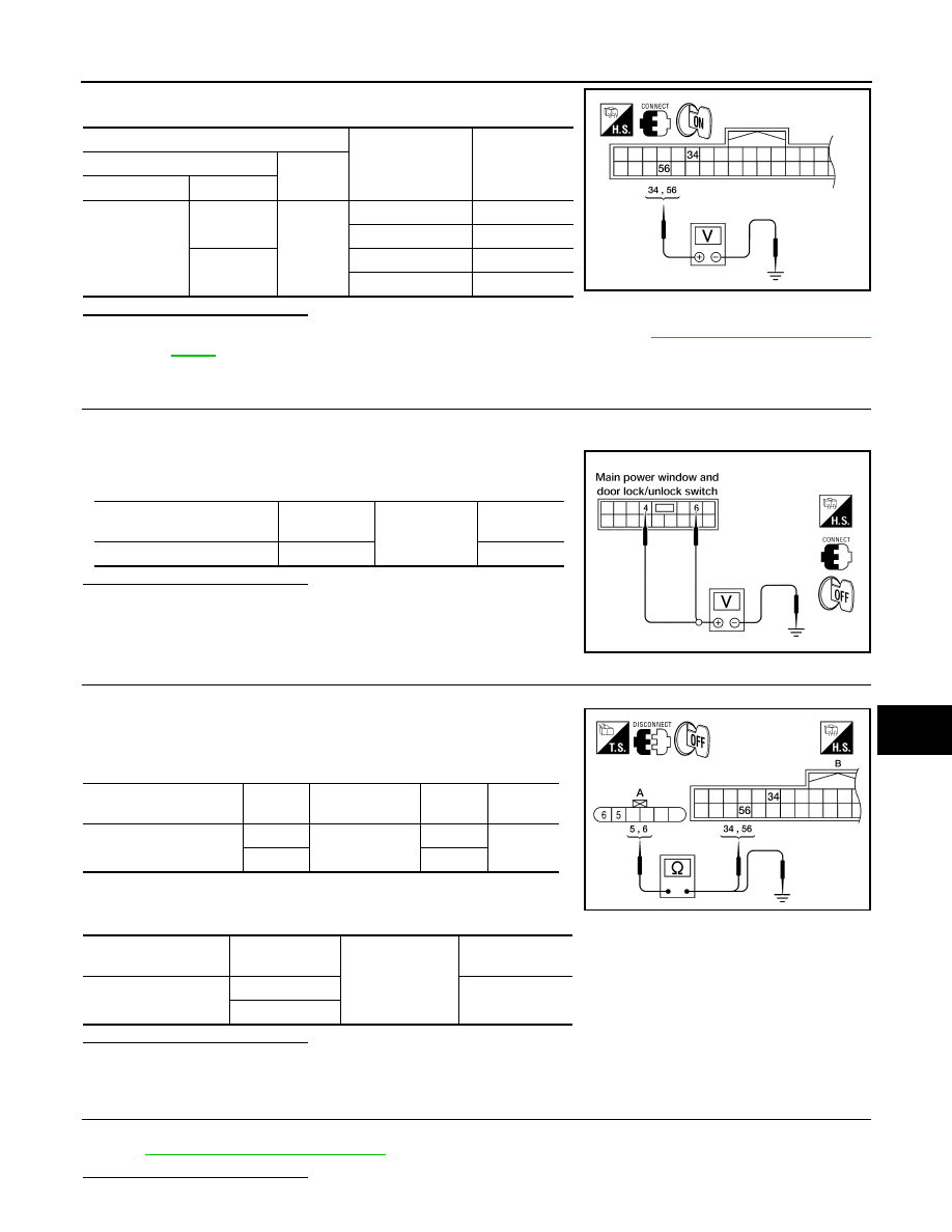
2. Check voltage between BCM connector and ground.

Is the inspection result normal?

YES

>> Replace main power window and door lock/unlock switch. Refer to 

PWC-98, "Removal and Instal-

lation"

.

NO

>> GO TO 2

2.

CHECK DOOR KEY CYLINDER SWITCH GROUND CIRCUIT

1. Turn ignition switch OFF.

2. Disconnect front door lock assembly LH (key cylinder switch) connector.

3. Check continuity between front door lock assembly LH (key cyl-

inder switch) connector and ground.

Is the inspection result normal?

YES

>> GO TO 3

NO

>> Repair or replace harness.

3.

CHECK DOOR KEY CYLINDER SIGNAL CIRCUIT

1. Disconnect BCM connector M18.

2. Check continuity between front door lock assembly LH (key cyl-

inder switch) connector D(10) terminals 5, 6 and BCM connector

M18 (B) terminals 34, 35.

3. Check continuity between front door lock assembly LH (key cyl-

inder switch) connector D10 (A) terminals 5, 6 and ground.

Is the inspection result normal?

YES

>> GO TO 4

NO

>> Repair or replace harness.

4.

CHECK DOOR KEY CYLINDER SWITCH

Check door key cylinder switch. 

Refer to 

SEC-90, "Component Inspection"

.

Is the inspection result normal?

Terminals

Key position

Voltage (V)

(Approx.)

(+)

(–)

BCM connector

Terminal 

M18

56

Ground

Lock

0

Neutral / Unlock

Battery voltage

34

Unlock

0

Neutral / Lock

Battery voltage

ALKIA0349ZZ

Front door lock assembly LH 

connector

Terminal

Ground

Continuity 

D10

4

Yes

LIIA0566E

Front door lock assembly 

LH connector

Terminal

BCM connector

Terminal

Continuity

A: D10

5

B: M18

34

Yes

6

56

Front door lock assem-

bly LH connector

Terminal

Ground

Continuity 

A: D10

5

No

6

ALKIA0350ZZ

SEC-90

< COMPONENT DIAGNOSIS >

[INTELLIGENT KEY SYSTEM]

KEY CYLINDER SWITCH

YES

>> Check intermittent incident. Refer to 

GI-42, "Intermittent Incident"

.

NO

>> Replace front door lock assembly LH (key cylinder switch). Refer to 

DLK-226, "FRONT DOOR

LOCK : Removal and Installation"

.

Component Inspection

INFOID:0000000004216085

COMPONENT INSPECTION

1.

CHECK DOOR KEY CYLINDER SWITCH

Check front door lock assembly LH (key cylinder switch).

Is the inspection result normal?

YES

>> Key cylinder switch is OK.

NO

>> Replace front door lock assembly LH (key cylinder switch). Refer to 

DLK-226, "FRONT DOOR

LOCK : Removal and Installation"

.

ALKIA0351ZZ

Terminal

Key position

Continuity

Front door lock assembly LH (key cylinder switch)

4

Unlock

Yes

Neutral / Lock

No

6

Lock

Yes

Neutral / Unlock

No

HORN

SEC-91

< COMPONENT DIAGNOSIS >

[INTELLIGENT KEY SYSTEM]

C

D

E

F

G

H

I

J

L

M

A

B

SEC

N

O

P

HORN

Description

INFOID:0000000004216087

Horn (high/low) is located inside of front bumper and operates when theft warning system is in alarm phase.

Component Function Check

INFOID:0000000004216088

1.

CHECK FUNCTION

1. Select HORN in “ACTIVE TEST” mode with CONSULT-III.

2. Check the horn (high/low) operation.

Is the operation normal?

YES

>> Inspection End.

NO

>> Refer to 

SEC-91, "Diagnosis Procedure"

.

Diagnosis Procedure

INFOID:0000000004216089

1.

CHECK HORN FUNCTION

Check horn function with horn switch
Do the horns sound?

YES

>> GO TO 2

NO

>> Refer to 

HRN-3, "Wiring Diagram"

.

2.

CHECK HORN RELAY POWER SUPPLY

1. Turn ignition switch ON.

2. Perform “ACTIVE TEST” (“HORN”) with CONSULT-Ill.

3. Using an analog voltmeter or an oscilloscope, check voltage

between IPDM E/R connector E17 terminal 44 and ground.

Is the inspection result normal?

YES

>> GO TO 4

NO

>> GO TO 3

3.

CHECK HORN RELAY CIRCUIT

1. Turn ignition switch OFF.

2. Disconnect IPDM E/R and horn relay connector.

Test item

Description

HORN

ON

Horn relay

ON (for 20 ms)

ALKIA0424ZZ

IPDM E/R

Ground

Test item

Voltage (V)

(Approx.)

Connector

Terminal

E17

44

Ground

HORN

ON

Battery voltage 

→ 0 → Battery voltage

Other than above

Battery voltage

SEC-92

< COMPONENT DIAGNOSIS >

[INTELLIGENT KEY SYSTEM]

HORN

3. Check continuity between IPDM E/R harness connector and

horn relay harness connector.

4. Check continuity between IPDM E/R harness connector and

ground.

Is the inspection result normal?

YES

>> GO TO 4

NO

>> Repair or replace harness.

4.

CHECK INTERMITTENT INCIDENT

Refer to 

GI-42, "Intermittent Incident"

.

Is the inspection result normal?

YES

>> Replace IPDM E/R.Refer to 

PCS-39, "Removal and Installation"

.

NO

>> Repair or replace the malfunctioning part.

IPDM E/R

Horn relay

Continuity

Connector

Terminal

Connector

Terminal

A: E17

44

B: H-1

1

Yes

IPDM E/R

Ground

Continuity 

Connector

Terminal

A: E17

44

Ground

No

ALKIA0425ZZ


Content   ..  1002  1003  1004  1005   ..