Nissan Altima HL32 Hybrid. Manual - part 96


  Index      Nissan     Nissan Altima HL32 Hybrid (2009 year) - Service and Repair Manual


Search            


Content   ..  94  95  96  97   ..


Nissan Altima HL32 Hybrid. Manual - part 96


BCS-82

< ECU DIAGNOSIS >

[BCM]

BCM (BODY CONTROL MODULE)

• CRNT: Displays when there is a malfunction now or after returning to the normal condition until turning igni-

tion switch OFF 

→ ON again.

• 1 - 39: Displayed if any previous malfunction is present when current condition is normal. It increases like 1

→ 2 → 3...38 → 39 after returning to the normal condition whenever ignition switch OFF → ON. The counter

remains at 39 even if the number of cycles exceeds it. It is counted from 1 again when turning ignition switch

OFF 

→ ON after returning to the normal condition if the malfunction is detected again.
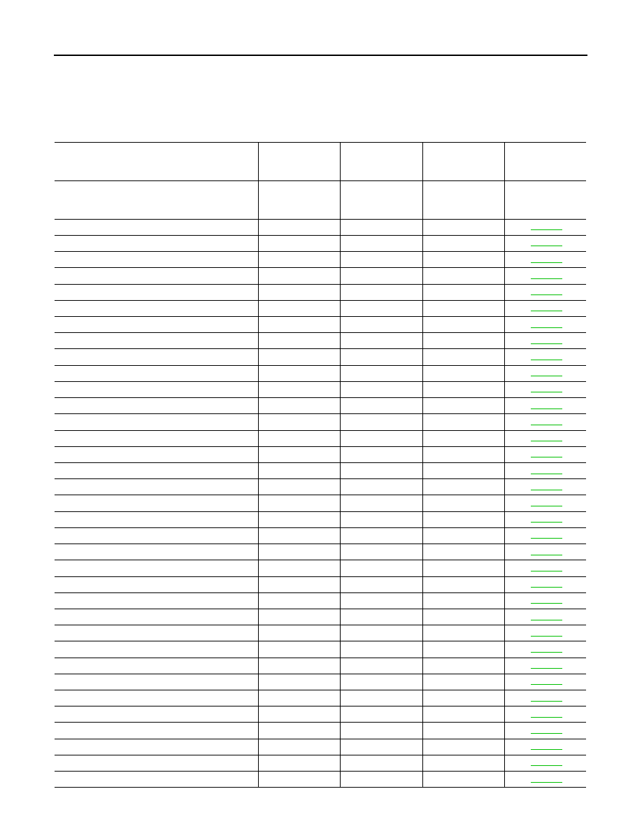
CONSULT display

Fail-safe

Intelligent Key 

warning lamp ON

Tire pressure 

monitor warning 

lamp ON

Reference page

No DTC is detected.
further testing
may be required.

U1000: CAN COMM CIRCUIT

BCS-37

U1010: CONTROL UNIT (CAN)

BCS-38

U0415: VEHICLE SPEED SIG

BCS-39

B2013: ID DISCORD BCM-S/L

×

SEC-30

B2014: CHAIN OF S/L-BCM

×

SEC-31

B2190: NATS ANTENNA AMP

×

SEC-40

B2191: DIFFERENCE OF KEY

×

SEC-43

B2192: ID DISCORD BCM-ECM

×

SEC-44

B2193: CHAIN OF BCM-ECM

×

SEC-45

B2553: IGNITION RELAY

PCS-53

B2555: STOP LAMP

SEC-46

B2556: PUSH-BTN IGN SW

×

SEC-49

B2557: VEHICLE SPEED

×

×

SEC-51

B2562: LOW VOLTAGE

BCS-40

B2563: HI VOLTAGE

×

×

BCS-41

B2601: SHIFT POSITION

×

×

SEC-52

B2602: SHIFT POSITION

×

×

SEC-55

B2603: SHIFT POSI STATUS

×

×

SEC-57

B2604: PNP SW

×

×

SEC-60

B2607: S/L RELAY

×

×

SEC-62

B2609: S/L STATUS

×

×

SEC-64

B260A: IGNITION RELAY

×

×

PCS-55

B260B: STEERING LOCK UNIT

×

SEC-68

B260C: STEERING LOCK UNIT

×

SEC-69

B260D: STEERING LOCK UNIT

×

SEC-70

B260F: ENG STATE SIG LOST

×

×

SEC-71

B2611: ACC RELAY

PCS-56

B2612: S/L STATUS

×

×

SEC-72

B2614: ACC RELAY CIRC

×

PCS-58

B2615: BLOWER RELAY CIRC

×

PCS-61

B2616: IGN RELAY CIRC

×

PCS-64

B2617: STARTER RELAY CIRC

×

×

SEC-76

B2618: BCM

×

×

PCS-67

B2619: BCM

×

×

SEC-78

B261A: PUSH-BTN IGN SW

×

SEC-79

BCS

BCM (BODY CONTROL MODULE)

BCS-83

< ECU DIAGNOSIS >

[BCM]

C

D

E

F

G

H

I

J

K

L

B

A

O

P

N

B261E: VEHICLE TYPE

×

× (Turn ON for 15 

seconds)

SEC-81

B2621: INSIDE ANTENNA

DLK-59

B2622: INSIDE ANTENNA

DLK-62

B2623: INSIDE ANTENNA

DLK-65

C1704: LOW PRESSURE FL

×

WT-8

C1705: LOW PRESSURE FR

×

WT-8

C1706: LOW PRESSURE RR

×

WT-8

C1707: LOW PRESSURE RL

×

WT-8

C1708: [NO DATA] FL

×

WT-14

C1709: [NO DATA] FR

×

WT-14

C1710: [NO DATA] RR

×

WT-14

C1711: [NO DATA] RL

×

WT-14

C1712: [CHECKSUM ERR] FL

×

WT-16

C1713: [CHECKSUM ERR] FR

×

WT-16

C1714: [CHECKSUM ERR] RR

×

WT-16

C1715: [CHECKSUM ERR] RL

×

WT-16

C1716: [PRESSDATA ERR] FL

×

WT-18

C1717: [PRESSDATA ERR] FR

×

WT-18

C1718: [PRESSDATA ERR] RR

×

WT-18

C1719: [PRESSDATA ERR] RL

×

WT-18

C1720: [CODE ERR] FL

×

WT-16

C1721: [CODE ERR] FR

×

WT-16

C1722: [CODE ERR] RR

×

WT-16

C1723: [CODE ERR] RL

×

WT-16

C1724: [BATT VOLT LOW] FL

×

WT-16

C1725: [BATT VOLT LOW] FR

×

WT-16

C1726: [BATT VOLT LOW] RR

×

WT-16

C1727: [BATT VOLT LOW] RL

×

WT-16

C1729: VHCL SPEED SIG ERR

×

WT-19

C1734: CONTROL UNIT

×

WT-20

CONSULT display

Fail-safe

Intelligent Key 

warning lamp ON

Tire pressure 

monitor warning 

lamp ON

Reference page

BCS-84

< SYMPTOM DIAGNOSIS >

[BCM]

COMBINATION SWITCH SYSTEM SYMPTOMS

SYMPTOM DIAGNOSIS

COMBINATION SWITCH SYSTEM SYMPTOMS

Symptom Table

INFOID:0000000004219006

1. Perform the data monitor of CONSULT-III to check for any malfunctioning item.
2. Check the malfunction combinations.

Malfunction item: 

×

3. Identify the malfunctioning part from the agreed combination and repair or replace the part.

Malfunction combi-

nation

Data monitor item

FR WI

PER HI

FR WIP

E

R LOW

F

R

 W

A

SH

ER

 S

W

FR WI

PER INT

INT VOL

U

ME

TURN SIG

N

AL R

TURN SIGNAL L

TA

IL

 LA

MP 

SW

H

I BEAM SW

HEAD LAMP SW 

1

HEAD LAMP SW 

2

P

ASSI

N

G

 SW

AU

T

O

 LI

GH

T

 S

W

FR F

O

SW

A

×

×

×

×

B

×

×

×

×

C

×

×

×

D

×

×

×

E

×

×

F

×

×

G

×

×

H

×

×

×

I

×

×

×

×

J

×

×

×

×

K

All  Items

L

If only one item is detected or the item is not applicable to the combinations A to K 

Malfunction 

combination

Malfunctioning part

Repair or replace

A

Combination switch INPUT 1 circuit

Inspect the combination switch input circuit applicable to the malfunctioning 
part. 

BCS-43, "Diagnosis Procedure"

B

Combination switch INPUT 2 circuit

C

Combination switch INPUT 3 circuit

D

Combination switch INPUT 4 circuit

E

Combination switch INPUT 5 circuit

F

Combination switch OUTPUT 1 circuit

Inspect the combination switch output circuit applicable to the malfunction-
ing part. 

BCS-45, "Diagnosis Procedure"

G

Combination switch OUTPUT 2 circuit

H

Combination switch OUTPUT 3 circuit

I

Combination switch OUTPUT 4 circuit

J

Combination switch OUTPUT 5 circuit

K

BCM

Replace BCM. Refer to 

BCS-87, "Removal and Installation"

.

L

Combination switch

Replace the combination switch. Refer to 

EXL-168, "Removal and Installa-

tion"

.

BCS

PREPARATION

BCS-85

< PREPARATION >

[BCM]

C

D

E

F

G

H

I

J

K

L

B

A

O

P

N

PREPARATION

PREPARATION

Special Service Tool

INFOID:0000000004476274

The actual shapes of Kent-Moore tools may differ from those of special service tools illustrated here.

Commercial Service Tools

INFOID:0000000004476275

Tool number
(Kent-Moore No.)
Tool name

Description

(J-44615)
Air bag lock master key set

Removing and installing air bag lock

LRS191

Tool name

Description

Power tools

Loosening bolts, nuts and screws

PIIB1407E


Content   ..  94  95  96  97   ..