Nissan Altima HL32 Hybrid. Manual - part 86


  Index      Nissan     Nissan Altima HL32 Hybrid (2009 year) - Service and Repair Manual


Search            


Content   ..  84  85  86  87   ..


Nissan Altima HL32 Hybrid. Manual - part 86


BCS-42

< COMPONENT DIAGNOSIS >

[BCM]

POWER SUPPLY AND GROUND CIRCUIT

POWER SUPPLY AND GROUND CIRCUIT

Diagnosis Procedure

INFOID:0000000004218993

1.

 CHECK FUSE AND FUSIBLE LINK

Check if the following BCM fuse or fusible link are blown.

Is the fuse or fusible link blown?

YES

>> Replace the blown fuse or fusible link after repairing the affected circuit.

NO

>> GO TO 2

2.

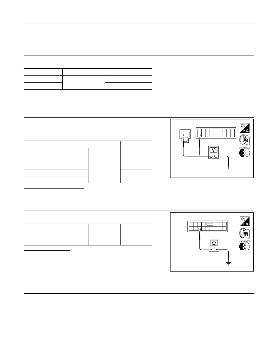
 CHECK POWER SUPPLY CIRCUIT

1. Turn ignition switch OFF.

2. Disconnect BCM.

3. Check voltage between BCM harness connector and ground.

Is the measurement normal?

YES

>> GO TO 3

NO

>> Repair or replace harness.

3.

 CHECK GROUND CIRCUIT

Check continuity between BCM harness connector and ground.

Does continuity exist?

YES

>> Inspection End.

NO

>> Repair or replace harness.

Special Repair Requirement

INFOID:0000000004218994

1.

 REQUIRED WORK WHEN REPLACING BCM

Initialize control unit. Refer to CONSULT-III operation manual.

>> Work End.

Terminal No.

Signal name

Fuse and fusible link No.

1

Battery power supply

J

11

10

Terminals

Voltage

(Approx.)

(+)

(

−)

BCM

Ground

Connector

Terminal

M16

1

Battery voltage

M17

11

ALCIA0025ZZ

BCM

Ground

Continuity

Connector

Terminal

M17

13

Yes

ALCIA0024ZZ

BCS

COMBINATION SWITCH INPUT CIRCUIT

BCS-43

< COMPONENT DIAGNOSIS >

[BCM]

C

D

E

F

G

H

I

J

K

L

B

A

O

P

N

COMBINATION SWITCH INPUT CIRCUIT

Diagnosis Procedure

INFOID:0000000004218995

1.

 CHECK INPUT 1 - 5 SYSTEM CIRCUIT FOR OPEN

1. Turn the ignition switch OFF.

2. Disconnect the BCM and combination switch.

3. Check continuity between BCM harness connector (A) and com-

bination switch harness connector (B).

Does continuity exist?

YES

>> GO TO 2

NO

>> Repair or replace harness.

2.

 CHECK INPUT 1 - 5 SYSTEM CIRCUIT FOR SHORT

Check for continuity between BCM harness connector and ground.

Does continuity exist?

YES

>> Repair or replace harness.

NO

>> GO TO 3

3.

 CHECK BCM OUTPUT VOLTAGE

1. Connect the BCM.

2. Check voltage between BCM harness connector and ground.

Is the measurement normal?

YES

>> GO TO 4

System

BCM

Combination switch

Continuity

Connector

Terminal

Connector

Terminal

INPUT 1

M19

(A)

95

M28

(B)

11

Yes

INPUT 2

97

9

INPUT 3

76

7

INPUT 4

96

10

INPUT 5

75

13

ALMIA0102ZZ

System

BCM

Ground

Continuity

Connector

Terminal

INPUT 1

M19

95

No

INPUT 2

97

INPUT 3

76

INPUT 4

96

INPUT 5

75

ALMIA0103ZZ

System

Terminals

Voltage

(Approx.)

(+)

(-)

BCM

Ground

Connector

Terminal

INPUT 1

M19

95

Refer to 

BCS-

52, "Physical 

Values"

.

INPUT 2

97

INPUT 3

76

INPUT 4

96

INPUT 5

75

ALMIA0104ZZ

BCS-44

< COMPONENT DIAGNOSIS >

[BCM]

COMBINATION SWITCH INPUT CIRCUIT

NO

>> Replace BCM. Refer to 

BCS-87, "Removal and Installation"

.

4.

 CHECK BCM INPUT SIGNAL

1. Connect the combination switch.

2. Turn ON any switch in the system that is malfunctioning.

3. Check voltage between BCM harness connector and ground.

Is the measurement normal when any of the switches are turned ON?

YES

>> Replace BCM. Refer to 

BCS-87, "Removal and Installation"

.

NO

>> Replace the combination switch. Refer to 

EXL-168, "Removal and Installation"

.

Special Repair Requirement

INFOID:0000000004218996

1.

 REQUIRED WORK WHEN REPLACING BCM

Initialize control unit. Refer to CONSULT-III operation manual NATS-IVIS/NVIS.

>> Work End.

System

Terminals

Voltage

(Approx.)

(+)

(-)

BCM

Ground

Connector

Terminal

INPUT 1

M19

95

Refer to 

BCS-

52, "Physical 

Values"

.

INPUT 2

97

INPUT 3

76

INPUT 4

96

INPUT 5

75

ALMIA0104ZZ

BCS

COMBINATION SWITCH OUTPUT CIRCUIT

BCS-45

< COMPONENT DIAGNOSIS >

[BCM]

C

D

E

F

G

H

I

J

K

L

B

A

O

P

N

COMBINATION SWITCH OUTPUT CIRCUIT

Diagnosis Procedure

INFOID:0000000004218997

1.

 CHECK COMBINATION SWITCH OUTPUTS

 With CONSULT-III perform combination switch "ACTIVE TEST" and operate combination switch outputs.

Refer to 

BCS-29, "COMB SW : CONSULT-III Function (BCM - COMB SW)"

.

Do combination switch outputs function?

YES

>> Combination switch outputs are OK.

NO

>> GO TO 2

2.

 CHECK OUTPUT 1 - 5 SYSTEM CIRCUIT FOR OPEN

1. Turn the ignition switch OFF.

2. Disconnect the BCM and combination switch.

3. Check continuity between BCM harness connector (A) and com-

bination switch harness connector (B).

Does continuity exist?

YES

>> GO TO 3

NO

>> Repair or replace harness.

3.

 CHECK OUTPUT 1 - 5 SYSTEM CIRCUIT FOR SHORT

Check for continuity between BCM harness connector and ground.

Does continuity exist?

YES

>> Repair or replace harness.

NO

>> GO TO 4

4.

 CHECK COMBINATION SWITCH OUTPUT VOLTAGE

System

BCM

Combination switch

Continuity

Connector

Terminal

Connector

Terminal

OUTPUT 1

M18

(A)

51

M28

(B)

12

Yes

OUTPUT 2

52

14

OUTPUT 3

53

5

OUTPUT 4

54

2

OUTPUT 5

50

8

ALMIA0105ZZ

System

BCM

Ground

Continuity

Connector

Terminal

OUTPUT 1

M18

51

No

OUTPUT 2

52

OUTPUT 3

53

OUTPUT 4

54

OUTPUT 5

50

ALMIA0106ZZ


Content   ..  84  85  86  87   ..