Nissan Altima HL32 Hybrid. Manual - part 60
AV-232
< COMPONENT DIAGNOSIS >
[BOSE AUDIO WITH NAVIGATION]
CAMERA IMAGE SIGNAL CIRCUIT (REAR VIEW CAMERA TO CAMERA CON-
TROL UNIT)
CAMERA IMAGE SIGNAL CIRCUIT (REAR VIEW CAMERA TO CAMERA
CONTROL UNIT)
Description
INFOID:0000000004219594
Rear view camera images are transmitted to the rear view camera control unit using the camera image signal
circuits.
Diagnosis Procedure
INFOID:0000000004219595
1.
CHECK CAMERA IMAGE SIGNAL CIRCUIT CONTINUITY
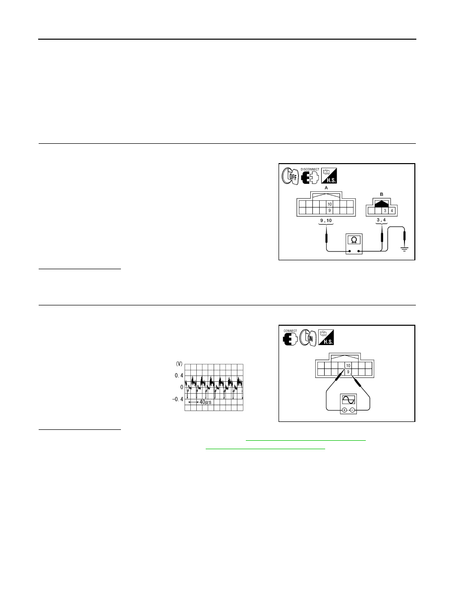
1. Turn ignition switch OFF.
2. Disconnect rear view camera control unit connector and rear view camera connector.
3. Check continuity between rear view camera control unit harness
connector B31 (A) terminals 9, 10 and rear view camera har-
ness connector B35 (B) terminals 3, 4.
4. Check continuity between rear view camera control unit harness
connector B31 (A) terminals 9, 10 and ground.
Is inspection result OK?
YES
>> GO TO 2
NO
>> Repair harness or connector.
2.
CHECK CAMERA IMAGE SIGNAL
1. Connect rear view camera control unit connector and rear view camera connector.
2. Turn ignition switch ON.
3. Check signal between rear view camera control unit harness
connector B31 terminals 10 and 9.
Is inspection result OK?
YES
>> Replace rear view camera control unit. Refer to
AV-294, "Removal and Installation"
NO
>> Replace rear view camera. Refer to
AV-293, "Removal and Installation"
.
9 - 4
: Continuity should exist.
10 - 3
: Continuity should exist.
9, 10 - Ground
: Continuity should not exist.
ALLIA0259ZZ
10 - 9
:
ALLIA0260ZZ
SKIB2251J