Nissan Altima HL32 Hybrid. Manual - part 9
AV-28
< COMPONENT DIAGNOSIS >
[BASE AUDIO]
SOUND SIGNAL CIRCUIT
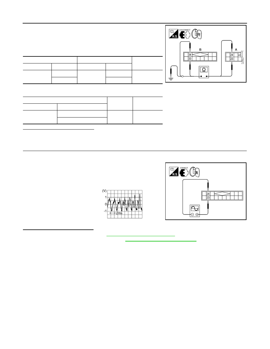
1. Turn ignition switch OFF.
2. Disconnect satellite radio tuner (factory installed) connector
B123 (A) and audio unit connector M45 (B).
3. Check continuity between satellite radio tuner (factory installed)
and audio unit.
4. Check continuity between satellite radio tuner (factory installed) and ground.
Are continuity results as specified?
YES
>> GO TO 2
NO
>> Repair harness or connector.
2.
CHECK RIGHT CHANNEL AUDIO SIGNAL
1. Connect satellite radio tuner (factory installed) and audio unit.
2. Turn ignition switch ON.
3. Check signal between satellite radio tuner (factory installed)
connector B123 terminals 23 and 24 with CONSULT-III or oscil-
loscope.
Are voltage readings as specified?
YES
>> Replace audio unit. Refer to
AV-46, "Removal and Installation"
.
NO
>> Replace satellite radio tuner. Refer to
AV-137, "Removal and Installation"
A
B
Continuity
Connector
Terminal
Connector
Terminal
B123
23
M45
33
Yes
24
34
A
—
Continuity
Connector
Terminal
B123
23
Ground
No
24
AWNIA0042ZZ
23 - 24
WKIA4550E
SKIB3609E