Nissan Frontier. Manual - part 924


  Index      Nissan     Nissan Frontier (2014 year) - Service and Repair Manual


Search            


Content   ..  922  923  924  925   ..


Nissan Frontier. Manual - part 924


CARGO LAMP CONTROL CIRCUIT

INL-23

< DTC/CIRCUIT DIAGNOSIS >

[WITH POWER DOOR LOCKS]

C

D

E

F

G

H

I

J

K

M

A

B

INL

N

O

P

1. Turn ignition switch OFF.

2. Disconnect cargo lamp switch connector.

3. Check continuity between cargo lamp switch terminals 1and 3.

Is the inspection result normal?

YES

>> Inspection End

NO

>> Replace cargo lamp switch.
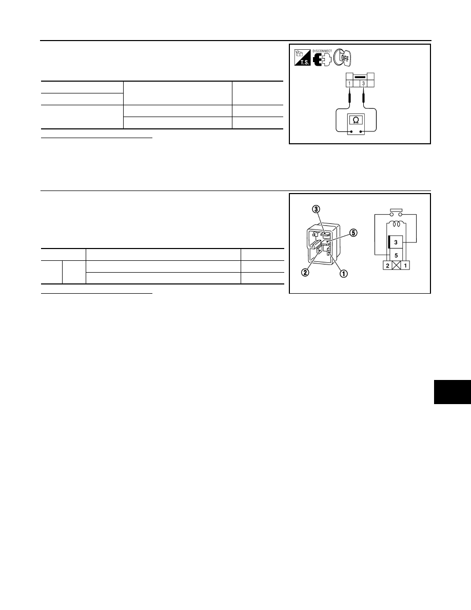
CARGO LAMP RELAY

1.

CHECK CARGO LAMP RELAY

1. Turn ignition switch OFF.

2. Disconnect cargo lamp relay.

3. Supply power to terminal 2 and ground to terminal 1 of the cargo

lamp relay.

4. Check continuity between cargo lamp relay terminals 3 and 5.

Is the inspection result normal?

YES

>> Inspection End

NO

>> Replace cargo lamp relay.

Cargo lamp switch

Condition

Continuity

Terminal

− 3

ON

Yes

OFF

No

AWLIA0804ZZ

Terminal

Condition

Continuity

3

5

Power and ground supplied to terminals 1 and 2

Yes

No power and ground supplied

No

SEF497Y

INL-24

< DTC/CIRCUIT DIAGNOSIS >

[WITH POWER DOOR LOCKS]

IGNITION KEYHOLE ILLUMINATION CONTROL CIRCUIT

IGNITION KEYHOLE ILLUMINATION CONTROL CIRCUIT

Description

INFOID:0000000009480145

Controls the ignition keyhole illumination (ground side) to turn the ignition keyhole illumination ON and OFF.

Component Function Check

INFOID:0000000009480146

CAUTION:

Before performing the diagnosis, check that the following is normal.

• Battery saver output/power supply circuit

• Ignition keyhole illumination bulb

1.

CHECK IGNITION KEYHOLE ILLUMINATION OPERATION

WITH CONSULT

1. Turn the ignition switch ON.

2. Select “IGN ILLUM” of BCM (INT LAMP) active test item.

3. While operating the test item, check that the ignition keyhole illumination turns ON/OFF

Is the inspection result normal?

YES

>> Ignition keyhole illumination circuit is normal.

NO

>> Refer to 

INL-24, "Diagnosis Procedure"

.

Diagnosis Procedure

INFOID:0000000009480147

Regarding Wiring Diagram information, refer to 

INL-37, "Wiring Diagram - With Power Door Lock System"

.

1.

CHECK IGNITION KEYHOLE OUTPUT

WITH CONSULT

1. Turn ignition switch ON.

2. Select “IGN ILLUM” of BCM (INT LAMP) active test item.

3. While operating the test item, check voltage between BCM con-

nector M18 terminal 1 and ground.

Is the inspection result normal?

YES

>> Ignition keyhole illumination control circuit is operating

normally.

Fixed ON>>GO TO 3.

Fixed OFF>> GO TO 2.

2.

CHECK IGNITION KEYHOLE ILLUMINATION OPEN CIRCUIT

ON

: Ignition keyhole illumination ON

OFF

: Ignition keyhole illumination OFF

Connector

Terminal

IGN ILLUM

Voltage

M18

1

Ground

ON

0V

OFF

Battery voltage

ALLIA0420GB

IGNITION KEYHOLE ILLUMINATION CONTROL CIRCUIT

INL-25

< DTC/CIRCUIT DIAGNOSIS >

[WITH POWER DOOR LOCKS]

C

D

E

F

G

H

I

J

K

M

A

B

INL

N

O

P

1. Turn ignition switch OFF.

2. Disconnect BCM connector M18 and ignition keyhole illumina-

tion connector.

3. Check continuity between BCM connector M18 (A) terminal 1

and ignition keyhole illumination connector M150 (B) terminal 2.

Is the inspection result normal?

YES

>> Check the ignition keyhole illumination for an open. If OK, replace the BCM. Refer to 

BCS-49,

"Removal and Installation"

. If NG, replace ignition keyhole illumination.

NO

>> Repair harness or connectors.

3.

CHECK IGNITION KEYHOLE ILLUMINATION SHORT CIRCUIT

1. Turn ignition switch OFF.

2. Disconnect BCM connector M18 and ignition keyhole illumina-

tion connector.

3. Check continuity between BCM connector M18 terminal 1 and

ground.

Is the inspection result normal?

YES

>> Check the ignition keyhole illumination for a short circuit.

If OK, replace the BCM. Refer to 

BCS-49, "Removal and

Installation"

. If NG, replace ignition keyhole illumination.

NO

>> Repair harness or connectors.

BCM

Ignition keyhole illumination

Continuity

Connector

Terminal

Connector

Terminal

M18 (A)

1

M150 (B)

2

Yes

WKIA5803E

Connector

Terminal

Continuity

M18

1

Ground

No

ALLIA0422GB

INL-26

< ECU DIAGNOSIS INFORMATION >

[WITH POWER DOOR LOCKS]

BCM (BODY CONTROL MODULE)

ECU DIAGNOSIS INFORMATION

BCM (BODY CONTROL MODULE)

Reference Value

INFOID:0000000010228011

NOTE:

The Signal Tech II Tool (J-50190) can be used to perform the following functions. Refer to the Signal Tech II

User Guide for additional information.

• Activate and display TPMS transmitter IDs

• Display tire pressure reported by the TPMS transmitter

• Read TPMS DTCs

• Register TPMS transmitter IDs

• Test remote keyless entry keyfob relative signal strength

VALUES ON THE DIAGNOSIS TOOL

Monitor Item

Condition

Value/Status

ACC ON SW

Ignition switch OFF or ON

Off

Ignition switch ACC

On

AIR COND SW

A/C switch OFF

Off

A/C switch ON

On

AIR PRESS FL

Front left tire air pressure value

kPa, kg/cm

2

, psi

AIR PRESS FR

Front right tire air pressure value

kPa, kg/cm

2

, psi

AIR PRESS RL

Rear left tire air pressure value

kPa, kg/cm

2

, psi

AIR PRESS RR

Rear right tire air pressure value

kPa, kg/cm

2

, psi

AUTO LIGHT SW

Lighting switch OFF

Off

Lighting switch AUTO

On

BRAKE SW

Brake pedal released

Off

Brake pedal applied

On

BUCKLE SW

Seat belt buckle unfastened

Off

Seat belt buckle fastened

On

BUZZER

Buzzer in combination meter OFF

Off

Buzzer in combination meter ON

On

CARGO LAMP SW

Cargo lamp switch OFF

Off

Cargo lamp switch ON

On

CDL LOCK SW

Door lock/unlock switch does not operate

Off

Press door lock/unlock switch to the LOCK side

On

CDL UNLOCK SW

Door lock/unlock switch does not operate

Off

Press door lock/unlock switch to the UNLOCK side

On

DOOR SW-AS

Front door RH closed

Off

Front door RH opened

On

DOOR SW-DR

Front door LH closed

Off

Front door LH opened

On

DOOR SW-RL

Rear door LH closed

Off

Rear door LH opened

On

DOOR SW-RR

Rear door RH closed

Off

Rear door RH opened

On


Content   ..  922  923  924  925   ..