Nissan Frontier. Manual - part 908


  Index      Nissan     Nissan Frontier (2014 year) - Service and Repair Manual


Search            


Content   ..  906  907  908  909   ..


Nissan Frontier. Manual - part 908


HAC-186

< DTC/CIRCUIT DIAGNOSIS >

[MANUAL A/C (TYPE 2)]

BLOWER MOTOR

Is inspection result normal?

YES

>> GO TO 13.

NO

>> Replace front blower motor. Refer to 

VTL-11, "Removal and Installation"

.

13.

CHECK FRONT BLOWER MOTOR RESISTOR

Check front blower motor resistor. Refer to 

HAC-186, "Front Blower Motor Component Inspection"

.

Is inspection result normal?

YES

>> GO TO 14.

NO

>> Replace front blower motor resistor. Refer to 

VTL-13, "Removal and Installation"

.

14.

CHECK FRONT BLOWER SWITCH

Check front blower switch. Refer to 

HAC-186, "Front Blower Motor Component Inspection"

.

Is inspection result normal?

YES

>> GO TO 15.

NO

>> Replace front blower switch. Refer to 

VTL-7, "Removal and Installation"

.

15.

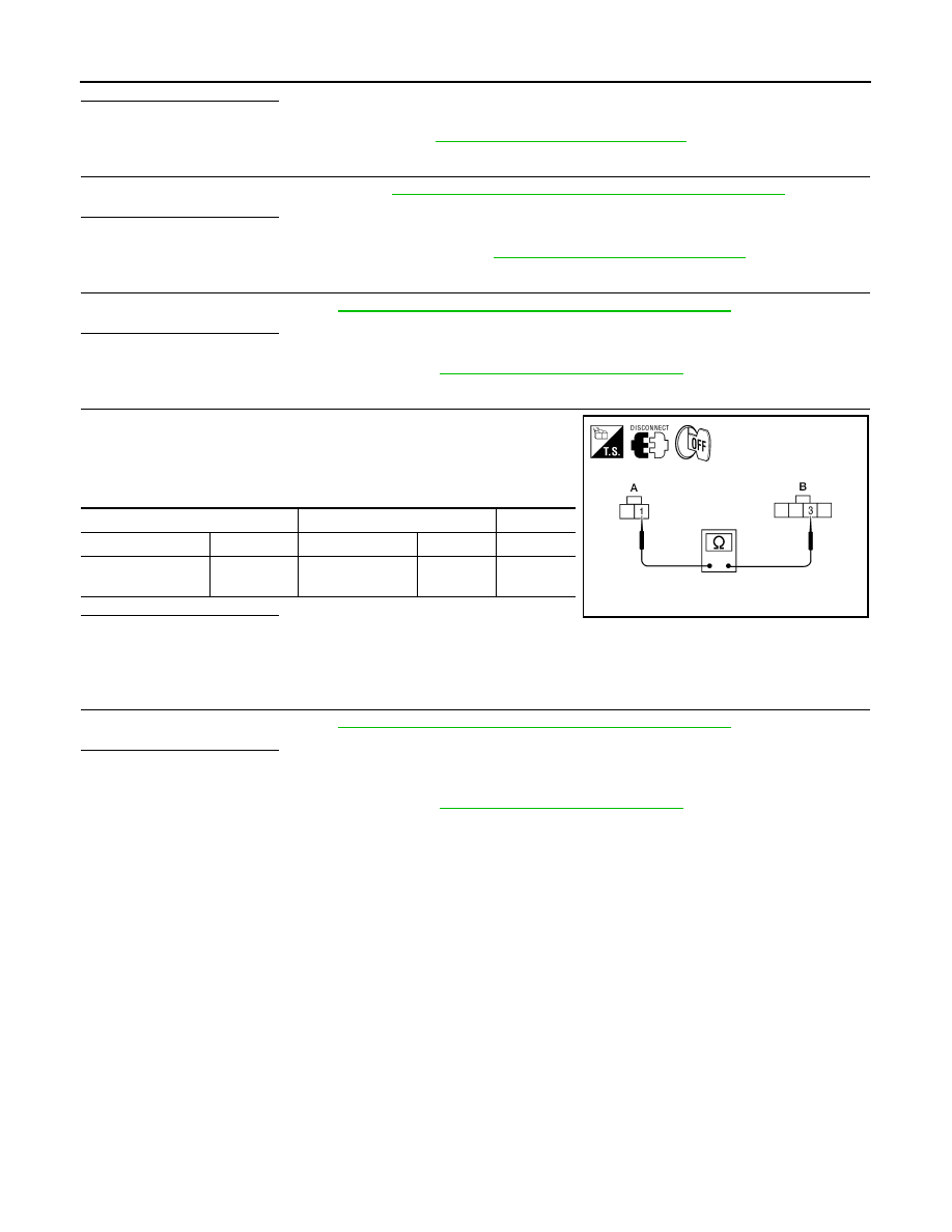
CHECK FRONT BLOWER MOTOR GROUND CIRCUIT TO FRONT BLOWER MOTOR RESISTOR

1. Disconnect front blower motor resistor harness connector.

2. Check continuity between front blower motor connector M62 (A)

terminal 1 and front blower motor resistor harness connector

M122 (B) terminal 3.

Is inspection result normal?

YES

>> Repair harness or connector between front blower

switch connector M51 terminal 8 and ground.

NO

>> Repair harness or connector between front blower motor resistor and front blower motor.

16.

CHECK FRONT BLOWER SWITCH

Check front blower switch. Refer to 

HAC-186, "Front Blower Motor Component Inspection"

.

Is inspection result normal?

YES

>> Repair harness or connector between front blower motor switch connector M51 terminal 8 and

front blower motor resistor connector M122 terminal 3.

NO

>> Replace front blower switch. Refer to 

VTL-7, "Removal and Installation"

.

SYMPTOM: Blower motor operation is malfunctioning.

Front Blower Motor Component Inspection

INFOID:0000000009478397

COMPONENT INSPECTION

Front Blower Motor Relay

A

B

Connector

Terminal Connector

Terminal 

Continuity

Front blower motor: 

M62

Front blower mo-

tor resistor: M122

3

Yes

WJIA1676E

BLOWER MOTOR

HAC-187

< DTC/CIRCUIT DIAGNOSIS >

[MANUAL A/C (TYPE 2)]

C

D

E

F

G

H

J

K

L

M

A

B

HAC

N

O

P

Check continuity between terminals by supplying 12 volts and

ground to coil side terminals of relay.

Front Blower Motor

Confirm smooth rotation of the blower motor.

• Ensure that there are no foreign particles inside the blower unit.

• Apply 12 volts to terminal 2 and ground to terminal 1 and verify that the motor operates freely and quietly.

Front Blower Switch

Check continuity between terminals at each front blower speed position.

Front Blower Motor Resistor

Check continuity between terminals. There will be resistance, but

there should not be an open or short between any two terminals.

LJIA0068E

WJIA0971E

HAC-188

< DTC/CIRCUIT DIAGNOSIS >

[MANUAL A/C (TYPE 2)]

MAGNET CLUTCH

MAGNET CLUTCH

System Description

INFOID:0000000009478398

SYSTEM DESCRIPTION

The front air control controls compressor operation based on intake temperature and a signal from ECM.

Low Temperature Protection Control

The front air control will turn the compressor ON or OFF as determined by a signal detected by the intake sen-

sor.

When intake air temperature is higher than 3.5

°C (38.3°F), the compressor turns ON. The compressor turns

OFF when intake air temperature is lower than 2.5

°C (36.5°F).

Magnet Clutch Component Function Check

INFOID:0000000009478399

SYMPTOM: Magnet clutch does not engage.

INSPECTION FLOW

1.

CONFIRM SYMPTOM BY PERFORMING OPERATIONAL CHECK - MAGNET CLUTCH

1. Rotate blower control dial clockwise. 
2. Rotate mode dial to vent (

) position.

3. Press A/C switch. Confirm that the compressor clutch engages (sound or visual inspection). 
Is the inspection result normal?

YES

>> Inspection End.

NO

>> Go to diagnosis procedure. Refer to 

HAC-188, "Magnet Clutch Diagnosis Procedure"

.

Magnet Clutch Diagnosis Procedure

INFOID:0000000009478400

Regarding Wiring Diagram information, refer to 

HAC-200, "Wiring Diagram - With Type 2"

.

DIAGNOSTIC PROCEDURE FOR MAGNET CLUTCH

SYMPTOM: Magnet clutch does not engage when A/C switch is ON.

1.

PERFORM IPDM E/R AUTO ACTIVE TEST

Refer to 

PCS-11, "CONSULT Function (IPDM E/R)"

.

Does magnet clutch operate?

YES

>> •

WITH CONSULT

GO TO 2.

WITHOUT CONSULT

AWIIA1787GB

MAGNET CLUTCH

HAC-189

< DTC/CIRCUIT DIAGNOSIS >

[MANUAL A/C (TYPE 2)]

C

D

E

F

G

H

J

K

L

M

A

B

HAC

N

O

P

GO TO 8.

NO

>> Check 10A fuse (No. 42, located in IPDM E/R), and GO TO 12.

2.

CHECK BCM INPUT (A/C COMPRESSOR ON) SIGNAL

Check A/C compressor ON/OFF signal. Refer to 

BCS-20, "AIR CONDITIONER : CONSULT Function (BCM -

AIR CONDITIONER)"

.

Is the inspection result normal?

YES

>> GO TO 3.

NO

>> GO TO 8.

3.

CHECK REFRIGERANT PRESSURE SENSOR

Check refrigerant pressure sensor. Refer to 

EC-458, "Diagnosis Procedure"

 (QR25DE) or 

EC-947, "Diagnosis

Procedure"

 (VQ40DE).

Is the inspection result normal?

YES

>> GO TO 4.

NO

>> Replace refrigerant pressure sensor. Refer to 

HA-36, "Removal and Installation"

.

4.

CHECK BCM INPUT (FAN ON) SIGNAL

Check FAN ON/OFF signal. Refer to 

BCS-20, "AIR CONDITIONER : CONSULT Function (BCM - AIR CONDI-

TIONER)"

.

Is the inspection result normal?

YES

>> GO TO 7.

NO

>> GO TO 5.

5.

CHECK CIRCUIT CONTINUITY BETWEEN BCM AND FRONT AIR CONTROL

1. Turn ignition switch OFF.

2. Disconnect BCM connector and front air control connector.

3. Check continuity between BCM harness connector M18 (A) ter-

minal 28 and front air control harness connector M49 (B) termi-

nal 18.

4. Check continuity between BCM harness connector M18 (A) ter-

minal 28 and ground.

Is the inspection result normal?

YES

>> GO TO 6.

NO

>> Repair harness or connector.

6.

CHECK VOLTAGE FOR FRONT AIR CONTROL (FAN ON SIGNAL)

A/C SW ON

: AIR COND SW ON

A/C SW OFF

: AIR COND SW OFF

BLOWER CONTROL DIAL 
ON

: FAN ON SIG ON

BLOWER CONTROL DIAL 
OFF

: FAN ON SIG OFF

A

B

Connector

Terminal Connector

Terminal 

Continuity

BCM: M18

28 

Front air control: 

M49

18

Yes

Connector

Terminal 

Ground 

Continuity

BCM: M18

28 

No

WJIA1627E


Content   ..  906  907  908  909   ..