Nissan Frontier. Manual - part 905
HAC-174
< DTC/CIRCUIT DIAGNOSIS >
[MANUAL A/C (TYPE 2)]
MODE DOOR MOTOR
Is the inspection result normal?
YES
>> GO TO 4.
NO
>> Replace front air control. Refer to
VTL-7, "Removal and Installation"
.
3.
CHECK MODE DOOR MOTOR PBR CIRCUITS FOR OPEN AND SHORT TO GROUND
1. Turn ignition switch OFF.
2. Disconnect the front air control harness connector M49 (A).
3. Check continuity between front air control harness connector M49 (A) terminals 23, 26 and the mode door
motor harness connector M142 (B) terminals 1, 3.
4. Check continuity between front air control harness connector M49 (A) terminals 23, 26 and ground.
Is the inspection result normal?
YES
>> GO TO 5.
NO
>> Repair or replace harness as necessary.
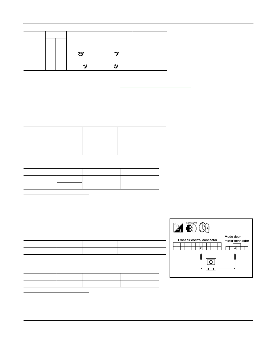
4.
CHECK PBR FEEDBACK SIGNAL CIRCUIT FOR OPEN AND SHORT TO GROUND
1. Check continuity between front air control harness connector
M49 terminal 21 and mode door motor harness connector M142
terminal 4.
2. Check continuity between front air control harness connector
M49 terminal 16 and ground.
Is the inspection result normal?
YES
>> GO TO 6.
NO
>> Repair or replace harness as necessary.
5.
CHECK FRONT AIR CONTROL FOR 5 VOLT REFERENCE (VREF), VREF RETURN, AND FEEDBACK
SIGNAL
1. Reconnect front air control harness connectors.
2. Turn ignition switch ON.
3. Check voltage between front air control harness connector M49 terminal 23 and terminal 26.
Connector
Terminals
Condition Voltage
(Approx.)
(+) (-)
M49
1
14
Rotating the mode control dial from
D/F (
) mode to VENT (
) mode
Battery voltage
14
1
Rotating the mode control dial from
VENT (
) mode to B/L (
) mode
Battery voltage
A
B
Continuity
Connector
Terminal
Connector
Terminal
M49
23
M142
3
Yes
26
2
Connector
Terminal
—
Continuity
M49 (A)
23
Ground
No
26
Connector
Terminal
Connector
Terminal
Continuity
M49
21
M142
4
Yes
Connector
Terminal
—
Continuity
M49
21
Ground
No
WJIA1089E