Nissan Frontier. Manual - part 887
HAC-102
< DTC/CIRCUIT DIAGNOSIS >
[MANUAL A/C (TYPE 1)]
MANUAL A/C IDENTIFICATION TABLE
DTC/CIRCUIT DIAGNOSIS
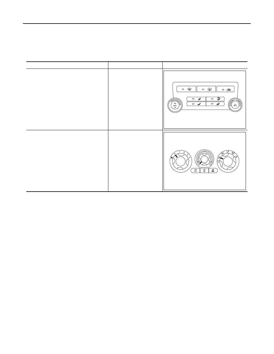
MANUAL A/C IDENTIFICATION TABLE
Application Table
INFOID:0000000009478334
Manual A/C Type
Description
Visual Identification
Manual A/C (Type 1)
Two Control Dial System
[with variable blower control
(VBC)]
Manual A/C (Type 2)
Three Control Dial System
[without variable blower con-
trol (VBC)]
AWIIA0481ZZ
AWIIA1228ZZ