Nissan Frontier. Manual - part 873


  Index      Nissan     Nissan Frontier (2014 year) - Service and Repair Manual


Search            


Content   ..  871  872  873  874   ..


Nissan Frontier. Manual - part 873


HAC-46

< DTC/CIRCUIT DIAGNOSIS >

[AUTOMATIC AIR CONDITIONER]

MAGNET CLUTCH

NO-1 >> If the voltage is approx. 5V when A/C switch is ON, replace front air control Refer to 

VTL-7,

"Removal and Installation"

.

NO-2 >> If the voltage is approx. 0V when A/C switch is OFF, replace BCM. Refer to 

BCS-49, "Removal

and Installation"

.

8.

CHECK REFRIGERANT PRESSURE SENSOR

1. Start engine.

2. Check voltage between ECM harness connector F57 terminal 63 and ground.

Is the inspection result normal?

YES

>> GO TO 9.

NO

>> Refer to 

EC-947, "Diagnosis Procedure"

.

9.

CHECK BCM INPUT (FAN ON) SIGNAL

Check FAN ON/OFF signal. Refer to 

HAC-19, "AIR CONDITIONER : CONSULT Function (BCM - AIR CONDI-

TIONER)"

.

Is the inspection result normal?

YES

>> GO TO 12.

NO

>> GO TO 10.

10.

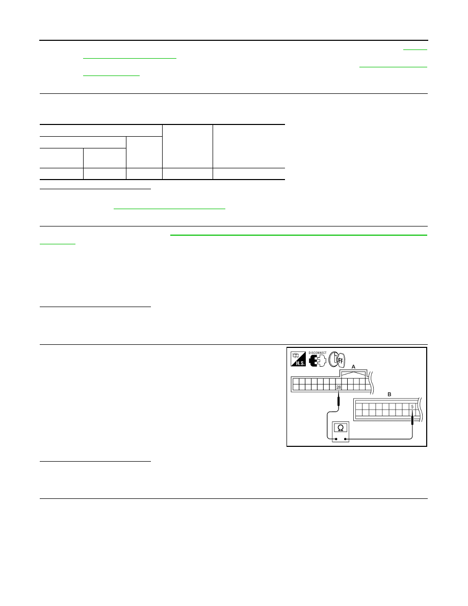
CHECK CIRCUIT CONTINUITY BETWEEN BCM AND FRONT AIR CONTROL

1. Turn ignition switch OFF.

2. Disconnect BCM connector and front air control connector.

3. Check continuity between BCM harness connector M18 (A) ter-

minal 28 and front air control harness connector M52 (B) termi-

nal 5.

4. Check continuity between BCM harness connector M18 (A) ter-

minal 28 and ground.

Is the inspection result normal?

YES

>> GO TO 11.

NO

>> Repair harness or connector.

11.

CHECK VOLTAGE FOR FRONT AIR CONTROL (FAN ON SIGNAL)

Terminals

Condition

Voltage

(+)

(-)

ECM con-

nector

Terminal No.

F57

63

Ground

A/C switch: ON

Approx. 0.36 - 3.88V

FRONT BLOWER CONTROL 
DIAL ON

: FAN ON SIG ON

FRONT BLOWER CONTROL 
DIAL OFF

: FAN ON SIG OFF

28 - 5

Continuity should exist.

28 - ground

Continuity should not exist.

AWIIA0418ZZ

MAGNET CLUTCH

HAC-47

< DTC/CIRCUIT DIAGNOSIS >

[AUTOMATIC AIR CONDITIONER]

C

D

E

F

G

H

J

K

L

M

A

B

HAC

N

O

P

1. Reconnect BCM connector and front air control connector.

2. Turn ignition switch ON.

3. Check voltage between front air control harness connector M52

terminal 5 and ground.

Is the inspection result normal?

YES

>> GO TO 12.

NO-1 >> If the voltage is approx. 5V when blower motor is ON, replace front air control. Refer to 

VTL-7,

"Removal and Installation"

.

NO-2 >> If the voltage is approx. 0V when blower motor is OFF, replace BCM. Refer to 

BCS-49, "Removal

and Installation"

.

12.

CHECK CAN COMMUNICATION

Check CAN communication. Refer to 

LAN-4, "System Description"

.

• BCM  –  ECM

• ECM – IPDM E/R

• ECM – Front air control
Is the inspection result normal?

YES

>> Replace IPDM E/R. Refer to 

PCS-28, "Removal and Installation of IPDM E/R"

.

NO

>> Repair or replace malfunctioning part(s).

Terminals

Condition

Voltage

(+)

(-)

Front air con-

trol connector

Terminal No.

M52

5

Ground

A/C switch: ON
Blower motor 
operates

Approx. 0V

A/C switch: OFF

Approx. 5V

AWIIA0419ZZ

HAC-48

< DTC/CIRCUIT DIAGNOSIS >

[AUTOMATIC AIR CONDITIONER]

AMBIENT SENSOR

AMBIENT SENSOR

Component Description

INFOID:0000000009478292

COMPONENT DESCRIPTION

Ambient Sensor

The ambient sensor (1) is attached on the radiator core support (left

side). It detects ambient temperature and converts it into a value

which is then input into the front air control.

AMBIENT TEMPERATURE INPUT PROCESS

The front air control includes a processing circuit for the ambient sensor input. However, when the tempera-

ture detected by the ambient sensor increases quickly, the processing circuit retards the front air control func-

tion. It only allows the front air control to recognize an ambient temperature increase of 0.33

°C (0.6°F) per 100

seconds.

This prevents constant adjustments due to momentary conditions, such as stopping after high speed driving.

Although the actual ambient temperature has not changed, the temperature detected by the ambient sensor

will increase. This is because the heat from the engine compartment can radiate to the front grille area, loca-

tion of the ambient sensor.

Ambient Sensor Diagnosis Procedure

INFOID:0000000009478293

Regarding Wiring Diagram information, refer to 

HAC-63, "Wiring Diagram - Automatic Air Conditioner"

.

DIAGNOSTIC PROCEDURE FOR AMBIENT SENSOR

SYMPTOM: Ambient sensor circuit is open or shorted. Using the

CONSULT, DTC B257B or B257C is displayed. Without CONSULT,

code 40 or 41 is indicated on front air control as a result of conduct-

ing the front air control self-diagnosis.

1.

CHECK VOLTAGE BETWEEN AMBIENT SENSOR AND GROUND

ALIIA0757ZZ

AWIIA0422GB

AMBIENT SENSOR

HAC-49

< DTC/CIRCUIT DIAGNOSIS >

[AUTOMATIC AIR CONDITIONER]

C

D

E

F

G

H

J

K

L

M

A

B

HAC

N

O

P

1. Disconnect ambient sensor connector.

2. Turn ignition switch ON.

3. Check voltage between ambient sensor harness connector E28

terminal 1 and ground.

Is the inspection result normal?

YES

>> GO TO 2.

NO

>> GO TO 4.

2.

CHECK CIRCUIT CONTINUITY BETWEEN AMBIENT SENSOR AND FRONT AIR CONTROL 

1. Turn ignition switch OFF.

2. Disconnect front air control connector.

3. Check continuity between ambient sensor harness connector

E28 (B) terminal 2 and front air control harness connector M52

(A) terminal 26.

Is the inspection result normal?

YES

>> GO TO 3.

NO

>> Repair harness or connector.

3.

CHECK AMBIENT SENSOR

Check the ambient sensor circuit. Refer to 

HAC-49, "Ambient Sensor Component Inspection"

.

Is the inspection result normal?

YES

>> 1. Replace front air control. Refer to 

VTL-7, "Removal and Installation"

.

2. GO TO 

HAC-20, "Front Air Control Self-Diagnosis"

 and perform self-diagnosis.

NO

>> 1. Replace ambient sensor. Refer to 

HA-35, "Removal and Installation"

.

2. GO TO 

HAC-20, "Front Air Control Self-Diagnosis"

 and perform self-diagnosis.

4.

CHECK CIRCUIT CONTINUITY BETWEEN AMBIENT SENSOR AND FRONT AIR CONTROL

1. Turn ignition switch OFF.

2. Disconnect front air control connector.

3. Check continuity between ambient sensor harness connector

E28 (B) terminal 1 and front air control harness connector M52

(A) terminal 25.

4. Check continuity between ambient sensor harness connector

E28 (B) terminal 2 and ground.

Is the inspection result normal?

YES

>> 1. Replace front air control. Refer to 

VTL-7, "Removal and Installation"

.

2. GO TO 

HAC-20, "Front Air Control Self-Diagnosis"

 and perform self-diagnosis.

NO

>> Repair harness or connector.

Ambient Sensor Component Inspection

INFOID:0000000009478294

COMPONENT INSPECTION

Ambient Sensor

After disconnecting ambient sensor connector E28, measure resistance between terminals 1 and 2 at sensor

component side, using the table below.

1 - Ground

: Approx. 5V

AWIIA0161ZZ

2 - 26

: Continuity should exist.

AWIIA1039ZZ

1 - 25

: Continuity should exist.

1 - Ground

: Continuity should not exist.

AWIIA1040ZZ


Content   ..  871  872  873  874   ..