Nissan Frontier. Manual - part 869


  Index      Nissan     Nissan Frontier (2014 year) - Service and Repair Manual


Search            


Content   ..  867  868  869  870   ..


Nissan Frontier. Manual - part 869


HAC-30

< DTC/CIRCUIT DIAGNOSIS >

[AUTOMATIC AIR CONDITIONER]

AIR MIX DOOR MOTOR

2. Using CONSULT, check "PAS MIX FDBCK" in "DATA MONITOR" mode in "HVAC". Refer to 

HAC-17,

"CONSULT Function (HVAC)"

.

3. Observe "PAS MIX FDBCK" voltage while rotating temperature control dial (passenger) between 32

°C

(90

°F) and 18°C (60°F).

Is the inspection result normal?

YES

>> • Air mix door motor (passenger) is OK.

• Inspect air mix door (passenger) for mechanical failure and repair if necessary. If air mix door

(passenger) is OK, refer to 

HAC-73, "Component Function Check"

 for insufficient cooling or

HAC-81, "Component Function Check"

 for insufficient heating.

NO

>> GO TO 2.

2.

CHECK AIR MIX DOOR MOTOR (PASSENGER) CIRCUITS FOR OPEN AND SHORT TO GROUND 

1. Turn ignition switch OFF.

2. Disconnect the front air control harness connector M52 and the air mix door motor (passenger) harness

connector M131.

3. Check continuity between front air control harness connector M52 terminals 2, 14 and the air mix door

motor (passenger) harness connector M131 terminals 5, 6.

4. Check continuity between front air control harness connector

M52 terminals 2, 14 and ground.

Is the inspection result normal?

YES

>> GO TO 3.

NO

>> Repair or replace harness as necessary.

3.

CHECK FRONT AIR CONTROL FOR AIR MIX DOOR MOTOR (PASSENGER) POWER AND GROUND 

1. Reconnect front air control harness connector.

2. Turn ignition switch ON.

3. Rotate temperature control dial (passenger) to 32

°C (90°F).

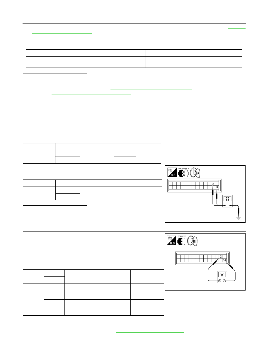
4. Check voltage between front air control harness connector M52

terminal 2 and terminal 14 while rotating temperature control dial

(passenger) to 18

°C (60°F) and back to 32°C (90°F).

Is the inspection result normal?

YES

>> GO TO 4.

NO

>> Replace front air control Refer to 

VTL-7, "Removal and Installation"

.

Monitor Item

Condition

Results

PAS MIX FDBCK

Rotate temperature control dial (passenger) be-

tween 32

°C (90°F) and 18°C (60°F)

Voltage varies between 0.2 and 4.8 volts.

Connector

Terminal

Connector

Terminal

Continuity

M52

14

M131

6

Yes

2

5

Connector

Terminal

Continuity

M52

14

Ground

No

2

AWIIA0386ZZ

Connector

Terminals

Condition Voltage 

(Approx.)

(+) (-)

M52

2

14

While rotating temperature control dial 
(passenger) from 32

°C (90°F) to 18°C 

(60

°F)

Battery voltage

14

2

While rotating temperature control dial 
(passenger) from 18

°C (60°F) to 32°C 

(90

°F)

Battery voltage

AWIIA0385ZZ

AIR MIX DOOR MOTOR

HAC-31

< DTC/CIRCUIT DIAGNOSIS >

[AUTOMATIC AIR CONDITIONER]

C

D

E

F

G

H

J

K

L

M

A

B

HAC

N

O

P

4.

CHECK AIR MIX DOOR MOTOR (PASSENGER) PBR CIRCUITS FOR OPEN AND SHORT TO GROUND 

1. Turn ignition switch OFF.

2. Disconnect the front air control harness connectors.

3. Check continuity between front air control harness connector M52 terminal 3 and M56 terminal 28 and air

mix door motor (passenger) harness connector M131 terminals 3, 1.

4. Check continuity between front air control harness connector M52 terminal 3, M56 terminal 28 and

ground.

Is the inspection result normal?

YES

>> GO TO 5.

NO

>> Repair or replace harness as necessary.

5.

CHECK PBR FEEDBACK SIGNAL CIRCUIT FOR OPEN AND SHORT TO GROUND 

1. Check continuity between front air control harness connector M56 terminal 29 and air mix door motor

(passenger) harness connector M131 terminal 2.

2. Check continuity between front air control harness connector

M56 terminal 29 and ground.

Is the inspection result normal?

YES

>> GO TO 6.

NO

>> Repair or replace harness as necessary.

6.

CHECK FRONT AIR CONTROL FOR 5 VOLT REFERENCE (VREF), VREF RETURN, AND FEEDBACK

SIGNAL 

1. Reconnect front air control harness connectors.

2. Turn ignition switch ON.

3. Check voltage between front air control harness connector M52

(B) terminal 3, and M56 (A) terminal 28.

Connector

Terminal

Connector

Terminal

Continuity

M52

3

M131

3

Yes

M56

28

1

Connector

Terminal

Continuity

M52

3

Ground

No

M56

28

Connector

Terminal

Connector

Terminal

Continuity

M56

29

M131

2

Yes

Connector

Terminal

Continuity

M56

29

Ground

No

AWIIA0132ZZ

A

B

Connector

Terminals

Connector

Terminals

Voltage (Approx.)

(+)

(-) 

M56

28

M52

3

5 Volts

AWIIA0813ZZ

HAC-32

< DTC/CIRCUIT DIAGNOSIS >

[AUTOMATIC AIR CONDITIONER]

AIR MIX DOOR MOTOR

4. Check voltage between front air control harness connector M56

terminal 29 and ground.

Is the inspection result normal?

YES

>> GO TO 7.

NO

>> Replace front air control. Refer to 

VTL-7, "Removal and

Installation"

.

7.

CHECK FRONT AIR CONTROL FOR FEEDBACK SIGNAL 

1. Reconnect the air mix door motor (passenger) harness connec-

tor M131.

2. Check voltage between front air control harness connector M56

terminal 29 and ground.

Is the inspection result normal?

YES

>> Inspect air mix door (passenger) for binding or mechani-

cal failure. If air mix door (passenger) moves freely,

replace front air control. Refer to 

VTL-7, "Removal and

Installation"

.

NO

>> Replace the air mix door motor (passenger). Refer to 

VTL-23, "Removal and Installation"

.

Connector

Terminal

Voltage (Approx.)

M56

29

Ground

0 Volts

AWIIA0131ZZ

Connector

Terminal

Voltage (Approx.)

M56

29

Ground

0.2 to 4.8 Volts

AWIIA0131ZZ

INTAKE DOOR MOTOR

HAC-33

< DTC/CIRCUIT DIAGNOSIS >

[AUTOMATIC AIR CONDITIONER]

C

D

E

F

G

H

J

K

L

M

A

B

HAC

N

O

P

INTAKE DOOR MOTOR

System Description

INFOID:0000000009478282

SYSTEM DESCRIPTION

SYMPTOM:

• Intake door motor does not operate normally.

• Intake door does not change.

SYSTEM DESCRIPTION

Component Parts

Intake door control system components are:

• Front air control

• Intake door motor (PRB built into the intake door motor)

• In-vehicle sensor

• Ambient sensor

• Optical sensor

• Intake sensor

System Operation

The intake door control determines the intake door position based on the position of the recirculation switch.

When the recirculation switch is depressed the intake door motor rotates closing off the fresh air inlet and

recirculating the cabin air. If the recirculation switch is depressed again, the intake door motor rotates in the

opposite direction, again allowing fresh air into the cabin.

In the AUTO mode, the front air control determines the intake door position based on the ambient tempera-

ture, the intake air temperature and the in-vehicle temperature. When the DEF, D/F, FOOT or OFF switches

are pushed, the front air control sets the intake door at the fresh position.

Intake Door Control Specification

COMPONENT DESCRIPTION

WJIA1915E

WJIA0436E


Content   ..  867  868  869  870   ..