Nissan Frontier. Manual - part 845


  Index      Nissan     Nissan Frontier (2014 year) - Service and Repair Manual


Search            


Content   ..  843  844  845  846   ..


Nissan Frontier. Manual - part 845


GI-48

< BASIC INSPECTION >

SERVICE INFORMATION FOR ELECTRICAL INCIDENT

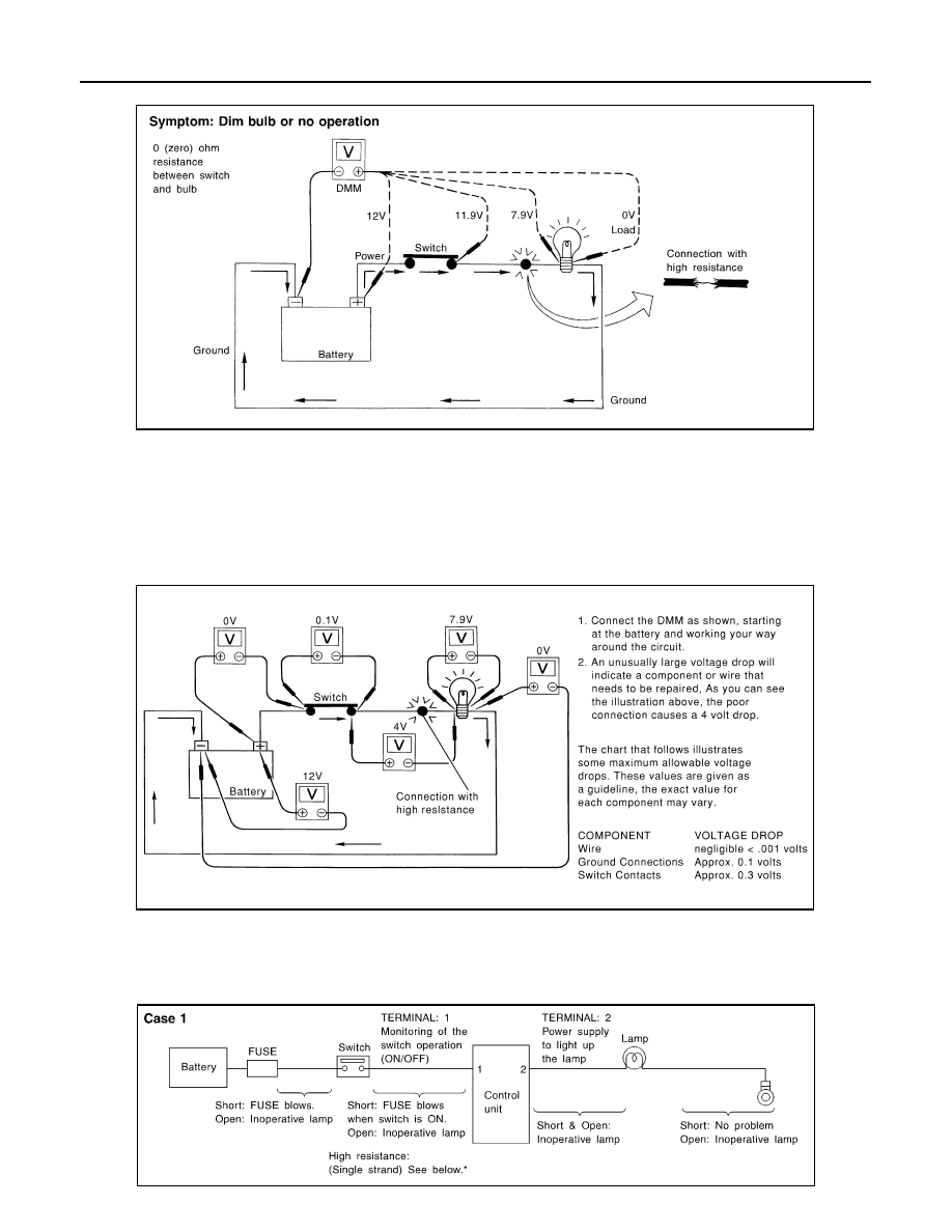
Note in the illustration that there is an excessive 4.1 volt drop between the battery and the bulb.

Measuring Voltage Drop — Step-by-Step

• The step-by-step method is most useful for isolating excessive drops in low voltage systems (such as those

in “Computer Controlled Systems”).

• Circuits in the “Computer Controlled System” operate on very low amperage.

• The (Computer Controlled) system operations can be adversely affected by any variation in resistance in the

system. Such resistance variation may be caused by poor connection, improper installation, improper wire

gauge or corrosion.

• The step by step voltage drop test can identify a component or wire with too much resistance.

CONTROL UNIT CIRCUIT TEST 

System Description

• When the switch is ON, the control unit lights up the lamp.

CASE 1

SGI974

SAIA0258E

MGI034A

SERVICE INFORMATION FOR ELECTRICAL INCIDENT

GI-49

< BASIC INSPECTION >

C

D

E

F

G

H

I

J

K

L

M

B

GI

N

O

P

INPUT-OUTPUT VOLTAGE CHART

• The voltage value is based on the body ground.
• *: If high resistance exists in the switch side circuit (caused by a single strand), terminal 1 does not detect battery voltage. Control unit

does not detect the switch is ON even if the switch does not turn ON. Therefore, the control unit does not supply power to light up the
lamp.

CASE 2

INPUT-OUTPUT VOLTAGE CHART

• The voltage value is based on the body ground.
• *: If high resistance exists in the switch side circuit (caused by a single strand), terminal 2 does not detect approx. 0V. Control unit

does not detect the switch is ON even if the switch does not turn ON. Therefore, the control unit does not control ground to light up the
lamp.

Terminal No.

Description

Condition

Value (Approx.)

In case of high resistance such as single 
strand (V) *

+

Signal name

Input/

Output

1

Body 
ground

Switch

Input

Switch ON

Battery voltage

Lower than battery voltage Approx. 8 (Ex-
ample)

Switch OFF

0 V

Approx. 0

2

Body 
ground

Lamp

Output

Switch ON

Battery voltage

Approx. 0 (Inoperative lamp)

Switch OFF

0 V

Approx. 0

Terminal No.

Description

Condition

Value (Approx.)

In case of high resistance such as single 
strand (V) *

+

Signal name

Input/

Output

1

Body 
ground

Lamp

Output

Switch ON

0V

Battery voltage (Inoperative lamp)

Switch OFF

Battery voltage

Battery voltage

2

Body 
ground

Switch

Input

Switch ON

0 V

Higher than 0 Approx. 4 (Example)

Switch OFF

5 V

Approx. 5

MGI035A

GI-50

< BASIC INSPECTION >

CONSULT CHECKING SYSTEM

CONSULT CHECKING SYSTEM

Description

INFOID:0000000009480236

NOTE:

This vehicle is diagnosed using CONSULT-III plus.

• When CONSULT is connected with a data link connector equipped

on the vehicle side, it will communicate with the control unit

equipped in the vehicle and then enable various kinds of diagnos-

tic tests.

• Refer to CONSULT-III plus Operation Manual for more information.

Function and System Application

INFOID:0000000009480237

x: Applicable
*1: With 4WD
*2: With electronic locking rear differential
*3: With automatic transmission
*4: With auto A/C
*5: With NAVI

CONSULT Data Link Connector (DLC) Circuit

INFOID:0000000009480238

INSPECTION PROCEDURE

BBIA0538E

Direct Diagnostic Mode

Description

ALL MODE A

W

D/4WD

*1

ABS

IPDM E/R

BC

M

DIFF LO

CK

*2

TRANSMISSION

*3

AIR B

A

G

MET

E

R/M

&

A

ENGINE

HV

AC

*4

MUL

T

I A

V

*5

ECU  Identification

The  ECU  part  number  is  displayed.

-

x

-

x

x

x

x

-

x

x

x

Self  Diagnostic  Result

The  ECU  self  diagnostic  results  are  displayed.

x

x

x

x

x

x

x

x

x

x

x

Data  Monitor

The  ECU  input/output  data  is  displayed  in  real  time.

x

x

x

x

x

x

x

x

x

x

x

Active  Test

The  ECU  activates  outputs  to  test  components.

-

x

x

x

-

-

-

-

x

-

-

Work support

The settings for ECU functions can be changed.

-

x

-

x

-

-

-

x

x

-

-

DTC Work Support

The status of system monitoring tests and the self 
diagnosis status/results can be confirmed.

-

-

-

-

-

x

-

-

x

-

-

TROUBLE DIAG 
RECORD

Self diagnostic history and trouble diagnosis 
records in ECU are displayed.

-

-

-

-

-

-

x

-

-

-

-

Configuration

• The vehicle specification can be read and saved.
• The vehicle specification can be written when re-

placing ECU.

-

-

-

x

-

x

-

-

-

-

x

Cause  of  Warning  Lamp

States  the  reason  the  air  bag  warning  lamp  is  ON.

-

-

-

-

-

-

x

-

-

-

-

CAN Diagnosis

This mode displays network diagnostic results of 
CAN communication using a diagram.

x

x

x

x

x

x

x

x

x

x

x

CAN Diag Support Mntr

The result of transmit/receive diagnosis of CAN 
communication is displayed.

x

x

x

x

x

x

x

x

x

x

x

CONSULT CHECKING SYSTEM

GI-51

< BASIC INSPECTION >

C

D

E

F

G

H

I

J

K

L

M

B

GI

N

O

P

If the CONSULT cannot diagnose the system properly, check the following items.

NOTE:

The CAN and DDL2 circuits from DLC pins 6, 7 and 14 may be connected to more than one system. A short in

any circuit connected to a control unit in one system may affect CONSULT access to other systems.

Symptom

Check item

CONSULT cannot access any 
system.

• CONSULT DLC power supply circuit (Terminal 8 and 16) and ground circuit (Terminal 4 and 5) 

CONSULT cannot access indi-
vidual system. (Other systems 
can be accessed.)

• Power supply and ground circuit for the control unit of the system (For detailed circuit, refer to wiring 

diagram for each system.)

• Open or short circuit between the system and CONSULT DLC (For detailed circuit, refer to wiring 

diagram for each system.)

• Open or short circuit CAN communication line. Refer to 

LAN-14, "Trouble Diagnosis Flow Chart"

.


Content   ..  843  844  845  846   ..