Nissan Frontier. Manual - part 842
GI-36
< PRECAUTION >
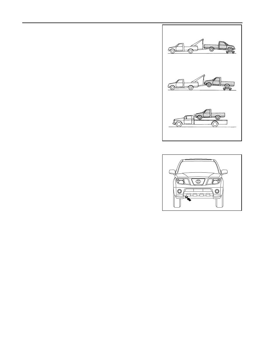
TOW TRUCK TOWING
NISSAN recommends that towing dollies be used when towing 4WD
equipped vehicles or place the vehicle on a flat bed truck.
CAUTION:
• Never tow 4WD models with any of the wheels on the ground
as this may cause serious and expensive damage to the
transfer case and transmission.
Towing Point
CAUTION:
Never tow the vehicle using only the towing points. To avoid
damaging the vehicle body, use proper towing equipment when
towing.
Vehicle Recovery (Freeing a stuck vehicle)
INFOID:0000000009480229
• Tow chains or cables must be attached only to the main structural members of the vehicle.
• Pulling devices should be routed so they do not touch any part of the suspension, steering, brake or
cooling systems
• Always pull the cable straight out from the front or rear of the vehicle. Never pull the vehicle at a
sideways angle.
• Pulling devices such as ropes or canvas straps are not recommended for use for vehicle towing or
recovery.
SGI973
LAIA0053E