Nissan Frontier. Manual - part 737


  Index      Nissan     Nissan Frontier (2014 year) - Service and Repair Manual


Search            


Content   ..  735  736  737  738   ..


Nissan Frontier. Manual - part 737


CAMSHAFT VALVE CLEARANCE

EM-137

< PERIODIC MAINTENANCE >

[VQ40DE]

C

D

E

F

G

H

I

J

K

L

M

A

EM

N

P

O

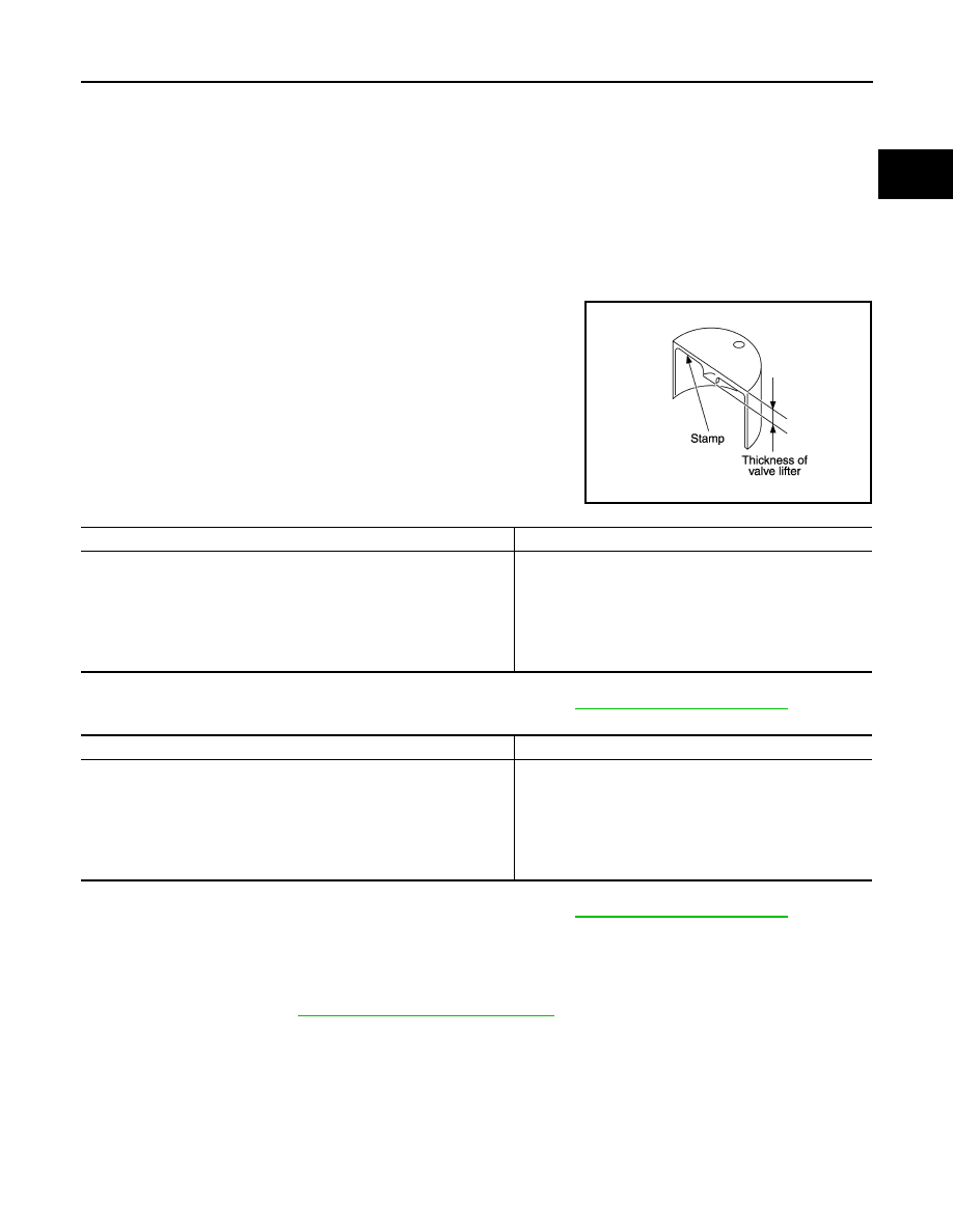
• Thickness of new valve lifter can be identified by stamp marks

on the reverse side (inside the cylinder).

Intake

Available thickness of valve lifter: 27 sizes with range 7.88 to 8.40 mm (0.3102 to 0.3307 in) in steps of

0.02 mm (0.0008 in) (when manufactured at factory). Refer to 

EM-247, "Standard and Limit"

.

Exhaust

Available thickness of valve lifter: 25 sizes with range 7.88 to 8.36 mm (0.3102 to 0.3291 in) in steps of

0.02 mm (0.0008 in) (when manufactured at factory). Refer to 

EM-247, "Standard and Limit"

.

CAUTION:

Install identification letter at the end and top, “U” and “N”, at each of proper positions. (Be care-

ful of mis-installation between intake and exhaust.)

6. Install selected valve lifter.
7. Install camshaft. Refer to 

EM-193, "Removal and Installation"

.

8. Manually turn crankshaft pulley a few turns. 
9. Make sure that the valve clearances for cold engine are within the specifications by referring to the speci-

fied values.

10. Installation of the remaining components is in the reverse order of removal.
11. Start the engine, and check for unusual noise and vibration.

Valve lifter thickness calculation:

t = t

1

+ (C

1

– C

2

)

t

= Valve lifter thickness to be replaced

t

1

= Removed valve lifter thickness

C

1

= Measured valve clearance

C

2

= Standard valve clearance:

Intake

: 0.30 mm (0.012 in)*

Exhaust

: 0.33 mm (0.013 in)*

*: Approximately 20

°C (68°F)

KBIA0119E

Stamp mark

Thickness

788U

7.88 mm (0.3102 in)

790U

7.90 mm (0.3110 in)

·

·

·

·

840U

8.40 mm (0.3307 in)

Stamp mark

Thickness

N788

7.88 mm (0.3102 in)

N790

7.90 mm (0.3110 in)

·

·

·

·

N836

8.36 mm (0.3291 in)

EM-138

< PERIODIC MAINTENANCE >

[VQ40DE]

COMPRESSION PRESSURE

COMPRESSION PRESSURE

Compression Pressure

INFOID:0000000009478105

CHECKING COMPRESSION PRESSURE

1. Warm up engine thoroughly. 
2. Release fuel pressure. Refer to 

EC-959, "Fuel Pressure Check"

.

3. Disconnect fuel pump fuse to avoid fuel injection during mea-

surement.

4. Remove intake manifold collector. Refer to 

EM-142, "Removal and Installation"

.

5. Remove spark plug from each cylinder. Refer to 

EM-132, "Removal and Installation"

.

6. Connect engine tachometer (not required in use of CONSULT).
7. Install compression tester with adapter onto spark plug hole.

• Use compression gauge whose pick up end inserted to spark

plug hole is smaller than 20 mm (0.79 in) in diameter. Other-

wise, it may be caught by cylinder head during removal.

8. Turn ignition switch to “START” for cranking. When the gauge pointer stabilizes, read the compression

pressure and engine rpm. Perform these steps to check each cylinder.

Compression pressure:

Unit: kPa (kg/cm

2

, psi) /rpm

CAUTION:

Always use a fully charged battery to obtain specified engine speed.

• If the engine speed is out of the specified range check the battery and recharge as necessary. Check

the engine speed again with the battery properly charged. 

BBIA0534E

PBIC0900E

SBIA0533E

Standard

Minimum

Differential limit between cylinders

 1,275 (13.0, 185) / 300

981 (10.0, 142) / 300

98 (1.0, 14) / 300

COMPRESSION PRESSURE

EM-139

< PERIODIC MAINTENANCE >

[VQ40DE]

C

D

E

F

G

H

I

J

K

L

M

A

EM

N

P

O

• If some cylinders have low compression pressure, pour a small amount of engine oil into the spark plug

hole of the cylinder to re-check it for compression.

- If the added engine oil improves the compression, piston rings may be worn out or damaged. Check the

piston rings and replace if necessary

- If the compression pressure remains at a low level despite the addition of engine oil, the valves may be

malfunctioning. Check the valves for damage. Replace the valve or valve seat accordingly.   

- If two adjacent cylinders have low compression pressure and their compression remains low even after

the addition of engine oil, cylinder head gaskets may be leaking. 

• If the compression pressure is below the minimum value, check the valve clearances and parts associ-

ated with the combustion chamber (valve, valve seat, piston, piston ring, cylinder bore, cylinder head,

cylinder head gasket). After repairing as necessary, measure the compression pressure again.

9. Install the components in the reverse order of removal.
10. Start the engine, and confirm that it runs smoothly.
11. Perform trouble diagnosis. If DTC appears, erase it. Refer to 

EC-607, "Description"

.

EM-140

< REMOVAL AND INSTALLATION >

[VQ40DE]

ENGINE ROOM COVER

REMOVAL AND INSTALLATION

ENGINE ROOM COVER

Removal and Installation

INFOID:0000000009478106

CAUTION:

Do not damage or scratch cover when installing or removing. 

REMOVAL

1. Remove the engine room cover bolts using power tool.
2. Lift up on engine cover firmly to dislodge snap fit mounts.

INSTALLATION

Installation is in the reverse order of removal.

WBIA0622E


Content   ..  735  736  737  738   ..